Do you have a question about the Yamaha WaveRunner XL760 and is the answer not in the manual?
Details model names and their indications for clarity.
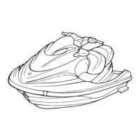
Explains how illustrations in the manual relate to procedures.
Indicates where to find additional information.
Highlights severe hazards that could result in injury or death.
Indicates special precautions to prevent damage.
Provides key information to make procedures easier or clearer.
Indicates parts subject to change during production.
Defines symbols used as thumb-tabs for chapter navigation.
Defines symbols indicating specific data types or measurements.
Defines symbols for applying lubricants, sealants, or other materials.
Locates and explains primary, engine, pump, and hull identification numbers.
Details crucial safety precautions, fire prevention, and personal protection.
Lists and describes specialized tools required for accurate assembly and tune-up.
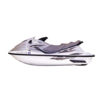
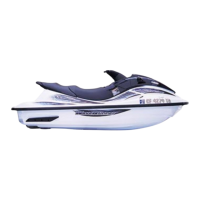
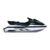
Provides overall technical data including dimensions and performance metrics.
Details specific measurements, wear limits, and tolerances for engine parts.
Lists required torque values for various engine and unit fasteners.
Illustrates the correct path and connections for fuel lines.
Illustrates the correct path and connections for control and electrical cables.
Provides a schedule for routine maintenance tasks based on operating hours.
Details inspection and adjustment procedures for periodic maintenance items.
Exploded diagrams and removal/installation charts for the fuel line system.
Exploded diagram and removal/installation chart for the oil tank.
Step-by-step procedure for removing the fuel tank assembly.
Exploded diagram and service points for fuel tank inspection.
Detailed procedures for removing the carburetor unit.
Exploded diagrams, charts, and service points for carburetor inspection.
Exploded diagram, chart, and service points for the fuel pump.
Exploded diagram, chart, and service points for the oil line.
Exploded diagram, chart, and service points for the oil pump.
Procedures for removing the engine unit, including exploded diagrams.
Exploded diagram and removal/installation procedures for the reed valve.
Exploded diagram and removal/installation procedures for the exhaust ring.
Step-by-step procedures for removing the exhaust chamber.
Exploded diagram and removal/installation procedures for the exhaust chamber.
Exploded diagrams and procedures for cylinder head removal and inspection.
Exploded diagrams, procedures, and inspection details for the cylinder.
Exploded diagrams, procedures, and inspection details for the piston.
Exploded diagrams and procedures for the flywheel magneto and base assembly.
Exploded diagrams and procedures for the electrical unit.
Exploded diagrams and procedures for the intermediate shaft housing.
Procedures for removing the jet pump unit, including exploded diagrams.
Exploded diagram and removal/installation for the nozzle deflector and reverse gate.
Exploded diagram and procedures for the nozzle, duct, and intake components.
Exploded diagrams and procedures for the impeller and drive shaft.
Exploded diagram and service points for the intake duct.
Exploded diagram and service points for the cooling and bilge systems.
Identifies and illustrates various electrical components and their locations.
Provides detailed wiring diagrams for the water vehicle's electrical systems.
Guides on performing electrical system analysis and voltage measurements.
Details on the ignition system, including wiring, components, and testing.
Information on the starting system, wiring diagrams, and component checks.
Wiring diagrams and testing procedures for the charging system.
Details on the indication system, sensors, meters, and warning lamps.
Exploded diagrams and procedures for removing the engine hood.
Exploded diagrams and procedures for removing the handlebars.
Exploded diagrams and procedures for handlebar components and installation.
Exploded diagrams and procedures for the steering column assembly.
Exploded diagram and procedures for the shift lever assembly.
Exploded diagrams and procedures for the engine hood components.
Exploded diagrams and procedures for the steering cable.
Exploded diagrams and procedures for throttle and choke cables.
Exploded diagram and procedures for the shift cable.
Exploded diagrams and procedures for the seat and storage box.
Exploded diagram and procedures for the battery case.
Exploded diagrams and procedures for the exhaust system.
Exploded diagrams and procedures for the deck.
Exploded diagrams and procedures for the gunwale.
Exploded diagram and installation procedures for the mat.
Exploded diagrams and procedures for hull repair and components.
General guidance and initial checks for troubleshooting.
A chart correlating symptoms with potential causes and reference chapters.
| Manufacturer | Yamaha |
|---|---|
| Model | WaveRunner XL760 |
| Category | Boat |
| Engine Type | 2-cylinder, 2-stroke |
| Displacement | 754 cc |
| Fuel Capacity | 13.2 gallons |
| Compression Ratio | 6.6:1 |
| Cooling System | Water-cooled |
| Starting System | Electric |
| Lubrication System | Oil Injection |
| Seating Capacity | 3 persons |
| Fuel Delivery | Carburetor |