Do you have a question about the Yamaha WaveRunner XL700 and is the answer not in the manual?
Details on primary, engine, pump, and hull identification numbers.
Lists recommended special tools for measurements and installation.
Provides model, dimensions, performance, engine, drive unit, and fuel/oil details.
Lists detailed technical specifications for engine components and electrical systems.
Specifies torque values for engine and jet unit parts during assembly.
Outlines recommended maintenance intervals for various systems based on usage.
Details inspection and adjustment procedures for trolling speed and carburetors.
Illustrates the correct routing for fuel lines and related components.
Step-by-step guide for removing the carburetor unit with exploded diagrams.
Covers adjustment of high/low speed screws and throttle/choke valve synchronization.
Provides instructions and diagrams for removing the main engine unit.
Step-by-step procedure for removing the reed valve assembly.
Details the removal process for the exhaust ring and related parts.
Guide for removing the exhaust chamber assembly.
Instructions for removing the cylinder head and associated components.
Procedure for removing and installing the cylinder.
Steps for removing and inspecting the piston, including clearance calculations.
Instructions for removing and installing the flywheel magneto and base assembly.
Identifies and lists electrical components with corresponding numbers.
Covers peak voltage measurement for various electrical systems.
Visual representation of the ignition system's electrical connections.
Electrical schematic for the starting system components.
Wiring diagram illustrating the charging system's electrical layout.
Schematic showing the wiring for the indication system (oil level).
Procedures for removing and installing throttle and choke cables.
Steps for removing and installing the exhaust system components.
Instructions for disassembling the main hull structure.
| Manufacturer | Yamaha |
|---|---|
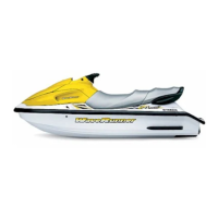
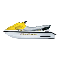
| Model | WaveRunner XL700 |
| Category | Boat |
| Engine Type | 2-cylinder, 2-stroke |
| Displacement | 701cc |
| Fuel Capacity | 13.2 gallons |
| Oil Capacity | 3.2 quarts |
| Compression Ratio | 7.2:1 |
| Starter System | Electric |
| Lubrication System | Oil injection |
| Cooling System | Water-cooled |
| Seating Capacity | 3 persons |
| Bore x Stroke | 81mm x 68mm |
| Fuel Delivery | Mikuni carburetor |