Do you have a question about the Yamaha XS360 and is the answer not in the manual?
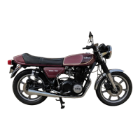
| Ignition | Battery and coil |
|---|---|
| Transmission | 6-speed |
| Front Suspension | Telescopic fork |
| Front Brake | Single disc |
| Rear Brake | Drum |
| Starting System | Electric and kick |
| Final Drive | Chain |
| Rear Tire | 3.50-18 |
| Fuel System | Carburetor |
| Rear Suspension | Swingarm with dual shocks |
| Dry Weight | 160 kg |
| Fuel Capacity | 12 liters |
Locate the engine number on a raised boss behind the right cylinder.
Find the frame number stamped on the right side of the steering lug.
Details on motor oil types, viscosity, and checking oil levels.
Information on recommended fork oil types and service intervals.
Instructions for checking and adjusting chain slack and lubrication.
Cable adjustment procedures for proper clutch operation.
Maintenance procedures for front and rear disc and drum brakes.
Adjustment and checking of throttle cable free-play.
Procedure for checking engine cylinder compression readings.
Steps for adjusting valve clearance when the engine is cold.
Location, inspection, and adjustment of contact breaker points.
Procedures for setting ignition timing for breaker point models.
Covers float level, synchronization, and idle speed/mixture settings.
Steps for safely removing and reinstalling the engine from the frame.
Detailed steps to remove the cylinder head assembly.
Procedures for cylinder and piston removal, inspection, and assembly.
Inspection and replacement of crankshaft bearings and components.
Servicing components beneath crankcase covers like clutch, oil pump.
Testing the alternator output and battery charging system.
Troubleshooting for breaker point and transistorized ignition systems.
Testing and servicing the starter motor, solenoid, and switch.
Troubleshooting for horn, brake, taillight, and turn signal lights.
Checking and troubleshooting neutral and oil pressure indicator lights.
Electrical schematic for the XS360-C model.
Electrical schematic for the XS360-2D model.
Electrical schematic for the XS400-D/E models.
Electrical schematic for the XS400F/2F models.
Electrical schematic for the XS400G/SG, 1981 models.
Procedure for removing and installing the front wheel.
Steps for removing and installing the rear wheel.
Maintenance and replacement procedures for disc brake pads and discs.
Removal, disassembly, and inspection of front fork components.
Adjustment and disassembly of steering stem bearings.