Do you have a question about the Yamaha XT660X 2007 and is the answer not in the manual?
Information regarding the manual's production and intended use by qualified mechanics.
Explains the meaning of symbols used to highlight important information.
Provides general specifications like dimensions, wheelbase, and ground clearance.
Covers engine type, displacement, oil grades, quantity, and oil pump specifications.
Covers rear wheel specifications and front tire details like type, size, and pressure.
Provides system voltage, ignition system type, timing, and advancer type details.
Specifies tightening torques for engine mounting bolts and O2 sensor components.
Explains routing for the rear brake hose, ensuring proper contact with the master cylinder.
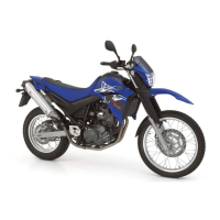
Details rear brake hose routing for XT660X, ensuring proper contact with the master cylinder.
Provides steps for removing and installing the motorcycle's cover components.
Outlines the procedure for removing and installing the front cowling and related parts.
Covers the removal and installation of the fuel tank and its associated components.
Explains how to check and adjust the drive chain slack for proper operation.
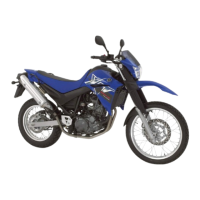
Covers checking tire pressure for the XT660R model, including load conditions.
Lists approved tire manufacturers, models, and sizes for front and rear wheels.
Provides steps for removing the rear wheel, chain cover, and related components for XT660X.
Covers lubricating and installing the rear wheel components for XT660R.
Provides steps for removing the swingarm, drive chain, and related parts for XT660X.
Provides steps for removing the exhaust pipes, mufflers, and O2 sensor.
Covers the removal of the cylinder head, spark plug, and related components.
Provides steps for removing the cylinder head, cylinder, and piston assembly.
Covers removing the radiator, cap, reservoir, and hoses for XT660X.
Identifies major components of the fuel injection system shown in a diagram.
Presents the comprehensive wiring diagram with component labels and wire color codes.
Lists fault codes, symptoms, fail-safe actions, startability, and driveability.
Provides step-by-step instructions for entering and setting up the diagnostic mode.
Provides countermeasures for Fault Code 12 related to the crankshaft position sensor.
Provides countermeasures for Fault Codes 13 & 14 related to the intake air pressure sensor.
Provides countermeasures for Fault Codes 15 & 16 related to the throttle position sensor.
Covers countermeasures for Fault Codes 19 (Sidestand switch) and 21 (Coolant temp sensor).
Provides countermeasures for Fault Code 22 related to the intake air temperature sensor.
Covers countermeasures for Fault Codes 24, 30, 31, 32 related to O2 sensor and motorcycle overturn.
Covers countermeasures for Fault Codes 33 (Ignition coil) and 41 (Lean angle cut-off switch).
Covers countermeasures for Fault Code 42 related to speed and neutral switches.
Covers countermeasures for Fault Codes 43 (Voltage) and 44 (EEPROM error).
Covers countermeasures for communication errors between ECU and meter.
Lists and illustrates electrical components used in the motorcycle system.
| Displacement | 660 cc |
|---|---|
| Compression Ratio | 10.0:1 |
| Fuel System | Fuel Injection |
| Ignition | TCI |
| Starter | Electric |
| Transmission | 5-speed |
| Final Drive | Chain |
| Width | 865 mm |
| Fuel Capacity | 15 liters |
| Bore x Stroke | 100 mm x 84 mm |
| Maximum Power | 48 PS (35.3 kW) @ 6, 000 rpm |
| Maximum Torque | 58.4 Nm (43 lb-ft) @ 5, 250 rpm |
| Front Suspension | Telescopic fork |
| Rear Suspension | Swingarm (link suspension) |
| Rear Brake | Single disc, 245 mm |
| Engine Type | Liquid cooled, 4-stroke, single cylinder, SOHC, 4-valves |
| Rear Tire | 160/60 R17 |