EasyManua.ls Logo

Yamaha YST- SW 012 User Manual

Yamaha YST- SW 012
16 pages
To Next Page IconTo Next Page
Page #1 background imageLoading...
Page #1 background image
CONTENTS
TO SERVICE PERSONNEL .......................................... 2
SPECIFICATIONS.......................................................... 3
INTERNAL VIEW ........................................................... 4
REAR PANELS .......................................................... 5~6
DISASSEMBLY PROCEDURES ............................... 7~8
BLOCK DIAGRAM ......................................................... 8
PRINTED CIRCUIT BOARD .......................................... 9
SCHEMATIC DIAGRAM .............................................. 10
PARTS LIST ........................................................... 11~15
2005 All rights reserved.
This manual is copyrighted by YAMAHA and may not be copied or
redistributed either in print or electronically without permission.
SUBWOOFER SYSTEM
YST-SW012
IMPORTANT NOTICE
This manual has been provided for the use of authorized YAMAHA
Retailers and their service personnel.
It has been assumed that basic service procedures inherent to the industry,
and more specifically YAMAHA Products, are already known and
understood by the users, and have therefore not been restated.
WARNING: Failure to follow appropriate service and safety
procedures when servicing this product may result in
personal injury, destruction of expensive components,
and failure of the product to perform as specified. For
these reasons, we advise all YAMAHA product owners
that any service required should be performed by an
authorized YAMAHA Retailer or the appointed service
representative.
IMPORTANT: The presentation or sale of this manual to any individual
or firm does not constitute authorization, certification or
recognition of any applicable technical capabilities, or
establish a principle-agent relationship of any form.
The data provided is believed to be accurate and applicable to the unit(s)
indicated on the cover. The research, engineering, and service departments
of YAMAHA are continually striving to improve YAMAHA products.
Modifications are, therefore, inevitable and specifications are subject to
change without notice or obligation to retrofit. Should any discrepancy
appear to exist, please contact the distributor's Service Division.
WARNING: Static discharges can destroy expensive components.
Discharge any static electricity your body may have
accumulated by grounding yourself to the ground buss in
the unit (heavy gauge black wires connect to this buss).
IMPORTANT: Turn the unit OFF during disassembly and part
replacement. Recheck all work before you apply power
to the unit.
YST-SW012
'05.12
100994
P.O.Box 1, Hamamatsu, Japan
SERVICE MANUAL
w
w
w
.
x
i
a
o
y
u
1
6
3
.
c
o
m
Q
Q
3
7
6
3
1
5
1
5
0
9
9
2
8
9
4
2
9
8
T
E
L
1
3
9
4
2
2
9
6
5
1
3
9
9
2
8
9
4
2
9
8
0
5
1
5
1
3
6
7
3
Q
Q
TEL 13942296513 QQ 376315150 892498299
http://www.xiaoyu163.com
Question and Answer IconNeed help?

Do you have a question about the Yamaha YST- SW 012 and is the answer not in the manual?

Yamaha YST- SW 012 Specifications

General IconGeneral
Driver Size8"
Frequency Response28 Hz - 200 Hz
Dynamic Power100 W
Weight8.5 kg
DriverCone
Power Output50W

Summary

To Service Personnel

Critical Components Information

Details on critical components and requirements for replacement parts to maintain original specifications.

Leakage Current Measurement

Procedure for verifying proper insulation of exposed conductive surfaces after service, including test parameters.

Chemical Content Notice

Important warning regarding lead in solder and potential chemical traces in components, with safety handling advice.

About Lead Free Solder

Information on lead-free solder used, recommended types for repair, and soldering precautions.

Specifications

Accessories

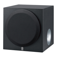
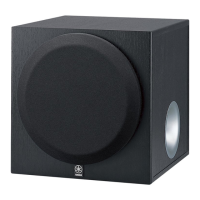
List of accessories provided with the YST-SW012 subwoofer system.

Dimensions

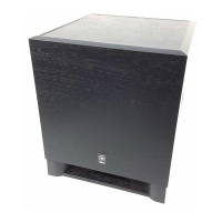
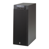
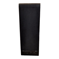
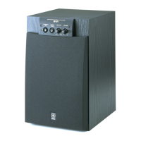
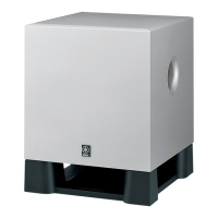
Detailed physical measurements of the subwoofer, including width, height, and depth, with diagrams.

Internal View

Rear Panels

Disassembly Procedures

Removal of Front Grille Assembly

Step-by-step instructions for safely removing the front grille assembly using a flatblade screwdriver.

Removal of Driver

Procedure for removing the driver unit, including disconnecting the connector and removing screws.

Removal of Rear Panel Assembly

Instructions for disassembling the rear panel assembly by removing screws.

Block Diagram

Printed Circuit Board

MAIN (3) P.C.B. (Side A)

Diagram showing the component layout for the Main Printed Circuit Board (3) on Side A.

MAIN (1) P.C.B. (Side A)

Diagram showing the component layout for the Main Printed Circuit Board (1) on Side A.

MAIN (5) P.C.B. (Side A)

Diagram showing the component layout for the Main Printed Circuit Board (5) on Side A.

MAIN (2) P.C.B. (Side A)

Diagram showing the component layout for the Main Printed Circuit Board (2) on Side A.

MAIN (7) P.C.B. (Side A)

Diagram showing the component layout for the Main Printed Circuit Board (7) on Side A.

MAIN (9) P.C.B. (Side A)

Diagram showing the component layout for the Main Printed Circuit Board (9) on Side A.

MAIN (10) P.C.B. (Side A)

Diagram showing the component layout for the Main Printed Circuit Board (10) on Side A.

Schematic Diagram

Pin Connection Diagrams

Diagrams illustrating the pin connections for transistors, diodes, and integrated circuits used in the system.

Parts List

Parts List: Carbon Resistors

Comprehensive list of carbon resistors, including values, part numbers, and power ratings.

Related product manuals