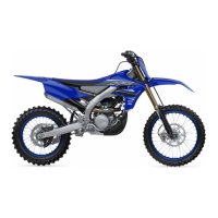
Do you have a question about the Yamaha YZ250FXM 2021 and is the answer not in the manual?
Essential safety guidelines for operating and maintaining the vehicle, including protective apparel and hazard avoidance.
Identifies the location of all important labels on the vehicle, such as warnings and information.
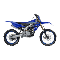
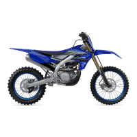
Provides a general overview and description of the vehicle’s main components and controls.
Details on vehicle and engine identification numbers and their locations for reference.
Lists and illustrates parts included with the vehicle, such as tools and accessories.
Crucial notes regarding preparation for disassembly, replacement parts, and fasteners.
Covers fundamental procedures for electrical system handling and basic service information.
Lists and describes special tools required for accurate adjustment and assembly.
Explains the function of various instruments and controls on the handlebar and chassis.
Provides instructions on fuel requirements, starting procedures, and engine break-in.
Information on the appropriateness of aftermarket tires and rims for optimal performance.
Instructions and precautions for safely transporting the motorcycle in another vehicle.
Provides dimensions, weight, and riding capacity of the vehicle.
Details engine components, fuel, oil, cooling system, and spark plug specifications.
Covers chassis details including wheels, tires, brakes, and suspension specifications.
Lists voltage, ignition system, charging system, and battery specifications for the vehicle.
General and specific torque values for fasteners during assembly and maintenance procedures.
Schedule of routine maintenance tasks based on operating hours or races for optimal performance.
Checklist for essential pre-ride inspections and general maintenance to ensure safe operation.
Procedures for checking and adjusting engine components like valve clearance and oil level.
Procedures for removing and installing the seat, side covers, and number plate.
Steps for removing, disassembling, checking, and assembling the front wheel.
Procedures for removing, checking, and installing the rear wheel and sprocket.
Details on removing, disassembling, checking, and installing the rear brake caliper and master cylinder.
Instructions for removing, checking, and installing the handlebar and its controls.
Steps for removing the front brake caliper from the fork.
Procedure for disassembling the front brake caliper into its components.
Inspection of caliper piston, cylinder, body, and fluid passages for wear or damage.
Steps for correctly assembling the front brake caliper after inspection or service.
Procedures for checking the front brake disc thickness and runout.
Guide to replacing the front brake pads without caliper disassembly.
Steps for removing the rear brake caliper from the bracket.
Procedure for disassembling the rear brake caliper into its components.
Inspection of caliper piston, cylinder, body, and fluid passages for wear or damage.
Steps for correctly assembling the rear brake caliper after inspection or service.
Procedures for checking the rear brake disc thickness and runout.
Guide to replacing the rear brake pads without caliper disassembly.
Steps for removing the handlebar, including grips and controls.
Inspection of the handlebar for bends, cracks, or damage.
Procedures for installing the handlebar and its associated components correctly.
Steps for removing the front fork legs from the chassis.
Procedure for disassembling the front fork legs into their individual parts.
Inspection of fork legs, inner tubes, outer tubes, and seals for wear or damage.
Steps for removing the lower bracket of the steering head assembly.
Procedure for checking bearings, races, and bracket for damage or looseness.
Instructions for installing the steering head bearings, races, and bracket.
Steps for removing the rear shock absorber assembly from the vehicle.
Inspection of the shock absorber rod, spring, guide, bearings, and bolts for damage.
Checking the connecting arm, relay arm, bearings, collars, and oil seals for wear.
Instructions for lubricating and installing the relay arm components.
Procedures for lubricating and installing the rear shock absorber assembly.
Steps for removing the swingarm, including measuring side play and vertical movement.
Inspection of the swingarm, pivot shaft, bushings, bearings, and oil seals for damage.
Procedures for lubricating and installing the swingarm and pivot shaft.
Steps for removing the drive chain from the motorcycle.
Procedure for measuring drive chain length and checking for stiffness or damage.
Inspection of the drive sprocket for tooth wear or damage.
Checking and replacing the rear wheel sprocket.
Steps for installing the drive chain, including master link fitting and riveting.
Diagrams illustrating the engine oil lubrication flow and system components.
Detailed steps for removing the engine from the chassis, including exhaust and electronic parts.
Procedures for removing, checking, and installing the camshafts and related components.
Steps for removing, checking, and installing the cylinder head and gasket.
Instructions for removing, checking, and installing valves, springs, and related parts.
Procedures for removing, checking, and installing the cylinder, piston, rings, and pin.
Steps for removing, checking, and installing the stator coil assembly, rotor, and Woodruff key.
Procedures for removing, checking, and installing the starter clutch and related gears.
Steps for removing, disassembling, checking, and assembling the starter motor.
Steps for removing the clutch assembly, including housing, plates, and springs.
Procedure for checking friction plates for damage, wear, and thickness.
Procedure for checking clutch plates for damage and warpage.
Checking clutch springs for damage and measuring their free length.
Inspection of clutch housing dogs for damage, pitting, or wear.
Checking push rods, bearings, washers, and ball for wear or damage.
Steps for removing the right crankcase cover to access the clutch components.
Procedures for installing the clutch components, including plates, springs, and boss.
Steps for removing the segment from the shift shaft assembly.
Inspection of the shift shaft, spring, guide, lever, and pawls for wear or damage.
Checking the stopper lever and its spring for wear, damage, or breakage.
Procedures for installing the stopper lever, segment, and shift shaft components.
Steps for removing the oil pump assembly and its cover.
Inspection of the oil pump cover, shaft, housing, and operation for wear or damage.
Steps for removing the balancer, drive gears, and weights.
Procedures for separating the crankcase halves, including bolt removal and dowel pin extraction.
Steps for removing bearings and oil seals from the crankcase.
Procedure for disassembling the crankcase, including removing dowel pins and bearings.
Checking the timing chain and guide for wear or damage.
Inspection of the crankcase for cracks, damage, and oil delivery passages.
Procedures for assembling the crankcase, including installing oil seals, bearings, and cover.
Steps for removing the crankshaft and balancer shaft assemblies.
Measuring crankshaft runout, assembly width, and checking for sprocket damage or oil passage obstructions.
Procedures for installing the crankshaft assembly using special tools.
Steps for removing the transmission, shift drum, and shift forks.
Checking shift fork cam follower, pawl, pin, spring, and guide for wear or damage.
Inspection of the shift drum groove and segment for damage or wear.
Measuring main axle runout and checking transmission gear movement.
Procedures for installing gears, collars, and circlips onto the main and drive axles.
Diagrams illustrating the layout of the cooling system components like radiator and water pump.
Steps for removing, checking, and installing the radiator and its hoses.
Procedures for removing, checking, and assembling the water pump and its components.
Procedures for removing and installing the fuel tank and fuel pump assembly.
Steps for removing, checking, and adjusting the throttle body and its related sensors.
Steps for removing the throttle body, including cables and joints.
Checking the injector for obstructions, deposits, damage, and resistance.
Inspection of the throttle body for cracks, damage, and fuel passages.
Procedure for measuring fuel line pressure at idle.
Steps for checking and adjusting the throttle position sensor angle using a diagnostic tool.
Covers circuit diagram, troubleshooting, and checking ignition system components.
Details circuit diagram, troubleshooting, and checking electric starting system components.
Includes circuit diagram, troubleshooting, and checking charging system components.
Covers circuit diagram, troubleshooting, and checking signaling system components.
Details circuit diagram, ECU self-diagnostics, and troubleshooting for the fuel injection system.
Schematic diagram of the ignition system's electrical connections.
Troubleshooting steps for ignition system failures like no spark or intermittent spark.
Schematic diagram of the electric starting system's wiring.
Troubleshooting steps when the starter motor fails to turn.
Schematic diagram of the charging system's electrical connections.
Troubleshooting steps when the battery is not being charged.
Schematic diagram of the signaling system's electrical connections.
Troubleshooting steps when the fuel level warning light fails to come on.
Schematic diagram of the fuel injection system's electrical connections.
Explanation of the ECU's self-diagnostic function and warning light indications.
Procedure for troubleshooting engine operation issues when the warning light is on.
Details on specific fault codes, their probable causes, and maintenance jobs.
Provides general guidelines and references for troubleshooting procedures.
Addresses engine starting issues when no fault code is detected.
Covers common clutch symptoms like slippage, dragging, and noise with possible causes and actions.
Lists symptoms related to transmission gear shifting and noise, with troubleshooting steps.
Addresses overheating and noise issues related to the cooling system and water pump.
Details common brake performance issues, possible causes, and corrective actions.
Explains symptoms and adjustments for front fork and rear suspension settings.
Covers issues like handlebar wobble, heavy steering, and front wheel vibration.
Identifies potential causes of noise from the cylinder head area.
Addresses noise originating from the timing chain and related components.
Lists fault codes for the fuel injection system and their corresponding items and pages.
Provides sensor displays and procedures for diagnostic codes related to sensor operation.
Details actuation and procedure for diagnostic codes related to actuator operation.
Covers chassis tuning aspects like sprocket selection, tire pressure, and fork/suspension settings.
Guidelines for adjusting tire pressure based on road surface conditions.
Explains how to adjust front fork characteristics based on air spring, spring preload, and damping force.
Lists parts for drive and rear wheel sprocket settings, including part numbers.
Describes how changing fork oil amount affects damping characteristics.
Instructions for setting spring preload and damping force after spring replacement.
Details the different front fork spring types and their specifications.
Explains how to set rear suspension preload and damping force based on rider feel.
Guidance on measuring and setting the sunken length for suspension components.
Procedures for adjusting spring preload and damping after replacing the rear shock spring.
Lists rear shock absorber spring specifications and preload adjusting positions.
Provides a table for adjusting front fork settings based on symptoms like stiffness and bottoming.
Offers guidance on adjusting rear shock absorber settings for stiffness and stability.
| Brand | Yamaha |
|---|---|
| Model | YZ250FXM 2021 |
| Category | Motorcycle |
| Language | English |
