EasyManua.ls Logo

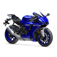
Yamaha YZF-R1 2022 User Manual

Yamaha YZF-R1 2022
95 pages
To Next Page IconTo Next Page
Page #1 background imageLoading...
Page #1 background image
Question and Answer IconNeed help?

Do you have a question about the Yamaha YZF-R1 2022 and is the answer not in the manual?

Yamaha YZF-R1 2022 Specifications

General IconGeneral
Bore x Stroke79.0 mm x 50.9 mm
Compression Ratio13.0:1
Fuel DeliveryFuel Injection with YCC-T and YCC-I
IgnitionTCI: Transistor Controlled Ignition
Final DriveChain
Front Tire120/70ZR17
Wheelbase1, 405 mm
Curb Weight201 kg
Length2, 055 mm
Width690 mm
Ground Clearance130 mm
Maximum Power200 PS @ 13, 500 rpm
Maximum Torque112.4 Nm @ 11, 500 rpm
Transmission6-speed
Front Suspension43 mm KYB inverted fork; fully adjustable
Rear SuspensionKYB single shock; fully adjustable
Front BrakesDual 320 mm hydraulic disc; ABS
Rear Brakes220 mm hydraulic disc; ABS
Rear Tire190/55ZR17
Fuel Capacity17 liters
Engine Type998cc, liquid-cooled inline 4-cylinder; DOHC, 4 valves per cylinder

Summary

1 Engine Specifications

2 Kit Parts

2-1 Installing Electrical Parts

Instructions for installing electrical components of the kit.

2. Cable Interface (2CR-8533A-70)

Self-Diagnosis Functions

Explanation of the ECU's self-diagnosis capabilities.

3. Wire Harness Set (B3L-F2590-70)

The name and function of each switch

YRC: Yamaha Ride Control

IMU: Inertial Measurement Unit

Explanation of the Inertial Measurement Unit's function.

PWR: Power Delivery Mode

Description of the four power delivery modes.

TCS: Spin control system

Explanation of the spin control system.

SCS: Slide control system

LCS: Launch control system

Explanation of the launch control system.

QSS: Quick shift system

Explanation of the quick shift system.

LIF: Lift control system

Explanation of the lift control system.

ERS: Electronic racing suspension

Description of the electronic racing suspension system.

EBM: Engine brake management system

Explanation of the engine brake management system.

About the front and rear wheel speed sensor

5. Headlight Harness Set (BX4-F4350-71)

6. Repair set

7. CCU COMP. (2KS-85800-72)

CCU Compatibility chart

Chart showing CCU compatibility by model year.

Usage

Connecting to the CCU

Instructions for connecting to the CCU via network.

Other usages

Meter setting

How to enable stop watch function for line passing detection on the meter.

2-2 Installing Engine Parts

8. Maintenance Set (B3L-MAINT-70)

List of parts for engine maintenance.

Angle tightening method

Method for tightening bolts using angle measurement.

Elongation control method

Method for tightening bolts using elongation measurement.

9. Spark Plug Set (14B-R465B-70)

10. Cylinder Head Gasket

Measuring the volume of the cylinder head combustion chamber

Procedure to measure combustion chamber volume.

11. Piston Set (2CR-116A0-71)

12. Connecting Rod Set (2CR-1165B-70)

13. Crankshaft (B3L-11400-70)

14. High-lift Camshafts for SBK

15. Cam Sprocket for SBK (B3L-12176-70)

Installation

<How to position at #1 cylinder's compression top dead point 105°>

Positioning guide for #1 cylinder's compression top dead point.

<Position to install the cam sprocket at #1 cylinder compression top dead point 105°>

Guide for installing cam sprocket at #1 cylinder's compression top dead point.

16. Cam Sprocket ASSY. for SST (B3L-12177-70)

17. Valve Spring Set (2CR-A2110-72)

18. Air Funnel Set (B3L-1440B-80)

Ycci System Control

Control of Ycci system and funnel using YMS.

19. AIS-plug Set (2CR-A4890-70)

20. Clutch Spring Spacer(B3L-16332-70)

21. Cluch boss set (B3L-16370-70)

22. Transmission Gear

Transmission Assembly

A Detail of installation of washer

Detailed steps for washer installation.

B Detail of installation of circlip

Detailed steps for circlip installation.

C Detail of installation of washer

Detailed steps for washer installation.

23. Mission Maintenance Set (2CR-A7000-70)

24. Drive Sprockets

25. Sprocket Nut Set (2CR-A7463-70)

26. Strainer Cover Set (2CR-13400-71)

Installation

Installation instructions for the strainer cover set.

Recommended oil level

27. Strainer Cover Set (B3L-13400-70)

2-3 Installing Chassis Parts

28. Spring Rear Shock

List of rear shock springs with rates.

29. Spring Front Fork

31. Front Spare Wheel ASS'Y (2CR-25100-70)

32. Rear Spare Wheel ASS'Y (B3L-25300-70)

33. Rear Sprocket

34. Front Caliper Piston set (B3L-25809-70)

35. Tube Guide (B3L-26243-70)

3 Tightening Torque List

Engine

Tightening torque specifications for engine components.

Tightening the Cylinder Head

Installing the Crankcase

Procedure to tighten the aluminum bolts

Procedure to install the engine (unchangeable)

Procedure to install the pivot shaft peripheral parts

4 Headlight Cord Wiring Diagram

Related product manuals