Do you have a question about the Yamatake MagneW3000 PLUS and is the answer not in the manual?
Importance of following safety precautions for correct installation, operation, and maintenance.
Explains the meaning of "Warning" and "Caution" symbols used in the manual.
Describes integral and remote configurations of the detector and converter.
Details DC power supply, analog output range, and resistive load.
Explains requirements for external power supply and resistive load.
Details DE protocol-based digital signal transmission and conversion.
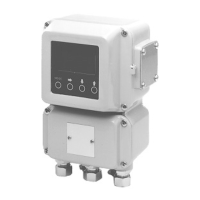
Describes the main components of the unit: converter, I/O card, data setting device, terminal box.
Explains the Name and function of each part: converter, data setting device, terminal box, nameplate.
Criteria for selecting an installation site to prevent malfunction and damage.
Describes three installation methods: integral, wall-mounted, and 2B pipe-mounted.
Covers wiring considerations: cable positions, power supply, grounding, and procedures.
Discusses dedicated and commercial cables, and their usage based on fluid conductivity.
Illustrates wiring diagrams for dedicated and commercially available cables.
Recommends cable types, shielding, sheath materials, conduit, and installation precautions.
Explains wiring for current output, with and without S-SFC communications.
Details wiring for pulse output, emphasizing voltage and polarity.
Explains wiring for contact input using semiconductor or no-voltage contacts.
Details wiring for contact output, emphasizing voltage and polarity.
Step-by-step procedure for starting up the electromagnetic flowmeter.
Explains the importance and methods for zero adjustment before operation.
Guides on adjusting the flowmeter for zero measurement when fluid is still.
Step-by-step procedure for performing zero adjustment using the S-SFC.
Steps to safely stop the flowmeter operation and shut off output.
Explains the four modes: MEASURING, OPERATOR'S, ENGINEERING, MAINTENANCE.
Procedure to enter Operator's Mode from Measuring Mode.
Lists settings and adjustments available in Operator's Mode.
Guides on setting damping time to reduce flow rate fluctuations.
Explains adjusting the flowmeter to zero when fluid is still.
Explains setting and changing the integration starting value of the built-in flow counter.
Explains resetting the current integrated flow rate and saving it to memory.
Describes changing contact output status when flow counter reaches a preset value.
Explains selecting flow rate indication modes: percent, actual rate, or integrated value.
Guides on selecting Engineering Mode or Maintenance Mode for settings or checks.
Lists settings and adjustments available in Engineering Mode.
Explains setting the ID code for the electromagnetic flowmeter.
Guides on setting functions: range, counter, contact input, and output.
Shows combinations for setting range, counter, contact input, and output functions.
| Repeatability | ±0.1% of reading |
|---|---|
| Measurement Principle | Faraday's law of electromagnetic induction |
| Type | Magnetic Flowmeter |
| Fluid Temperature | -20°C to +180°C |
| Lining Material | PFA, PTFE |
| Electrode Material | Hastelloy |
| Accuracy | ±0.5% of reading |
| Protection Degree | IP67 |
| Output Signal | 4 to 20 mA DC, Pulse, HART |
| Power Supply | 24 V DC |
| Measurement Range | 0 to 10 m/s |
| Operating Temperature | -20°C to +60°C |