SINGLE-CYLINDER ENGINES
73
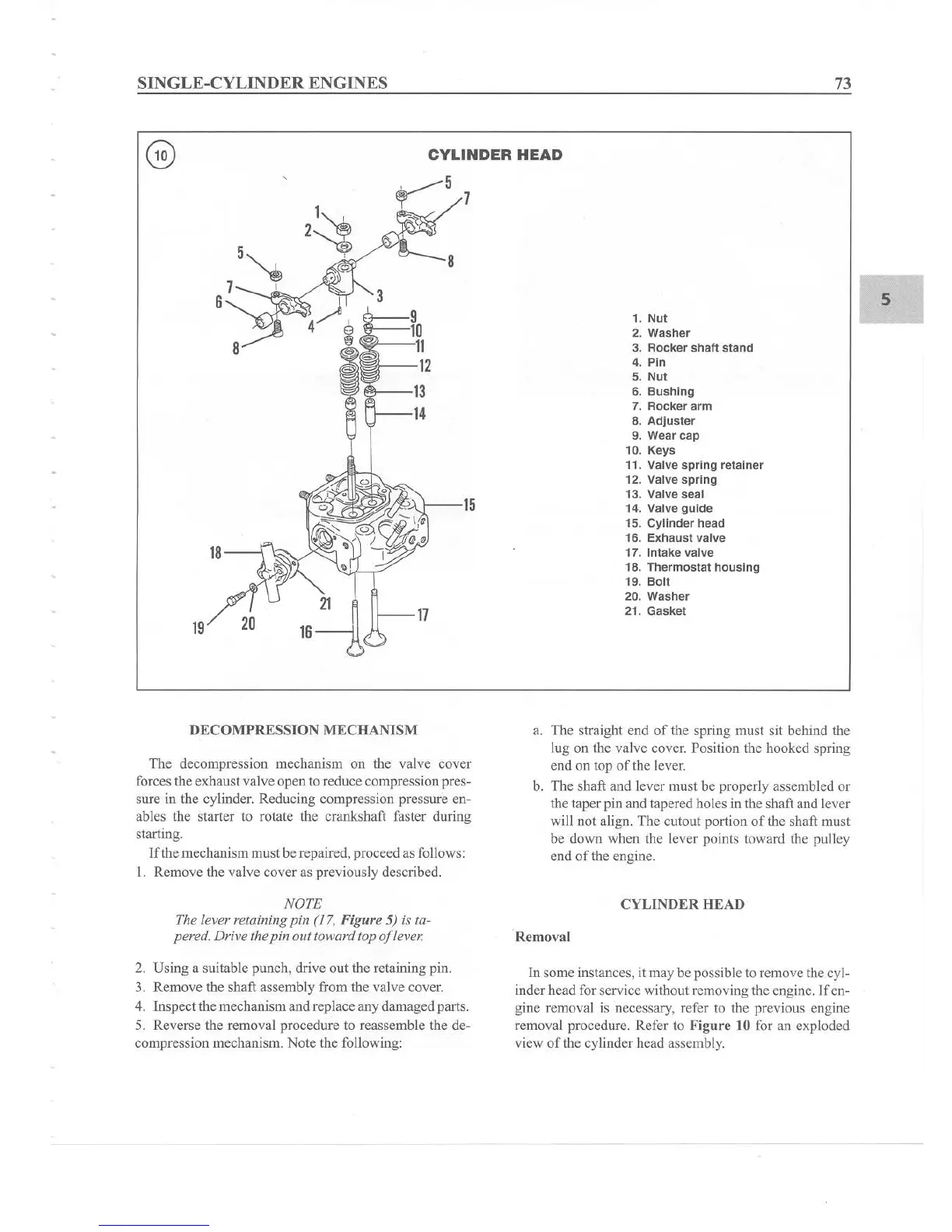
CYLINDER
HEAD
5
1.
Nut
2.
Washer
3. Rocker shaft stand
4. Pin
5.
Nut
6. Bu
shing
7. Rocker arm
8.
Adjuster
9. Wear cap
10. Keys
11. Valve sp
ring
retainer
12. Valve
spring
13. Valve seal
14. Valve
guide
15. Cy
linder
head
16.
Exhaust
valve
17. Intake valve
18.
Thermostat
housing
19. Boll
20.
Washer
21.
Gasket
8
~
5 7
3
~ ~
-
-
1
5
,1;
&;::
=1
10
j!
11
12
@>-
- 13
rL
-14
2
~
21
~
II
--
17
16
~
5"e
7 '
6 ,
6
~
18
19/1
DEC
OMPR
ESSION
MEC
HAl'iISM
The decompression mechanism on the valve cover
forces the exhaustvalve opento reduce compression pres-
sure in the cylinder. Reducing compression pressure en-
ables the starter to rotate the crankshaft faster during
starting.
If the mechanism mustbe repai red, proceed as follows:
1. Remove the valve cover as previously described.
a. The stra ight end
of
the spring must sit behind the
lug on the valve cover. Position the hooked spring
end on top
of
the lever.
b. The shaft
and
lever must be properly assembled or
the taper pin and tapered holes in the shaft and lever
will not align. The cutout portion of the shaft must
be down when the lever points toward the pulley
end
of
the engine.
NOTE
The lever retaining pin (17. Fi
gure
5) is ta-
pered. Drive the pin out toward top oflever:
CYLINDER HEAD
Remova l
2. Using a suitable punch, drive out the retain ing pin.
3. Remove the shaft assembly from the valve cover.
4. Inspect the mechanism and replace
any
damaged parts.
5. Reverse the removal procedure to reassemble the
de-
compression mechanism. Note the following:
In some instances, it may be possible to remove the cyl-
inder head for service without removing the engine. If
en-
gine removal is necessary, refer to the previous eng ine
removal procedure. R
ef
er to Figure to for an exploded
view
of
the cylinder head assembly.