16
Check the adjustment by placing the lift lever in the
BLADES STOP position. The deck should move up and
forward, allowing the belt to become loose. Start and
test for disengagement. Repeat procedure as
necessary.
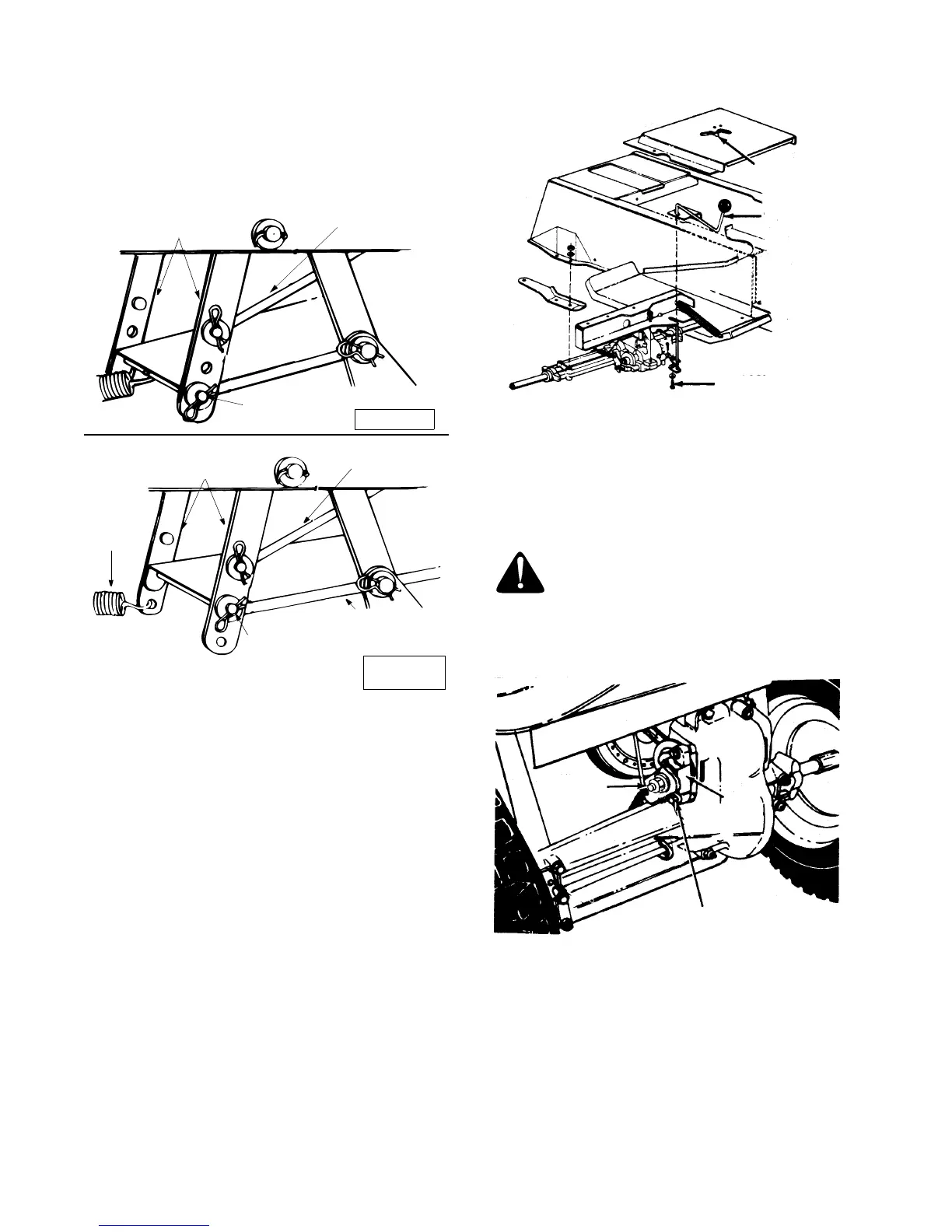
Figure 14
Neutral Adjustment
• Place the transmission in neutral. (The unit will
move freely when pushed forward and backward
with the parking brake released.)
• Loosen the bolt which secures the shift lever
assembly to the shift lever link. See Figure 15.
• Place the shift lever in the neutral slot.
See Figure 15.
• Tighten the bolt to 13 foot pounds.
Figure 15
Brake Adjustment
The brake is located by the right rear wheel inside the
frame. During normal operation of this machine, the
brake is subject to wear and will require periodic
examination and adjustment.See Figure 16.
WARNING: Do not have the engine
running when you adjust the brake.
To adjust the brake, adjust the nut so the brake starts to
engage when the brake lever is 1/4" to 5/16" away from
the axle housing.
Figure 16
Stabilizer Shaft
Assembly
Disengagement
Rod
Flat Washer
Hairpin Clip
Stabilizer Shaft
Assembly
Disengagement
Rod
Flat Washer
Hairpin Clip
38" Decks
Spring
Stabilizer Plate
42" and
46" Decks
Slot
Neutral
Lever
Shift
Loosen
Hex Bolt
Brake Lever
Nut
Disc
Brake
 Loading...