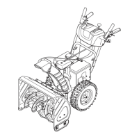
Fig. 3-8
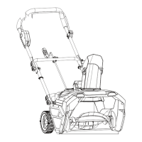
Place chute assembly onto chute base and secure chute •
control assembly to chute support bracket with clevis pin and
cotter pin removed earlier. See Fig. 3-4.
Finish securing chute control assembly to chute support •
bracket with wing nut and hex screw removed earlier. See
Fig. 3-5.
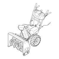
Guide the chute crank rod through the bracket located on •
the rear of the handle panel See Fig. 3-6.
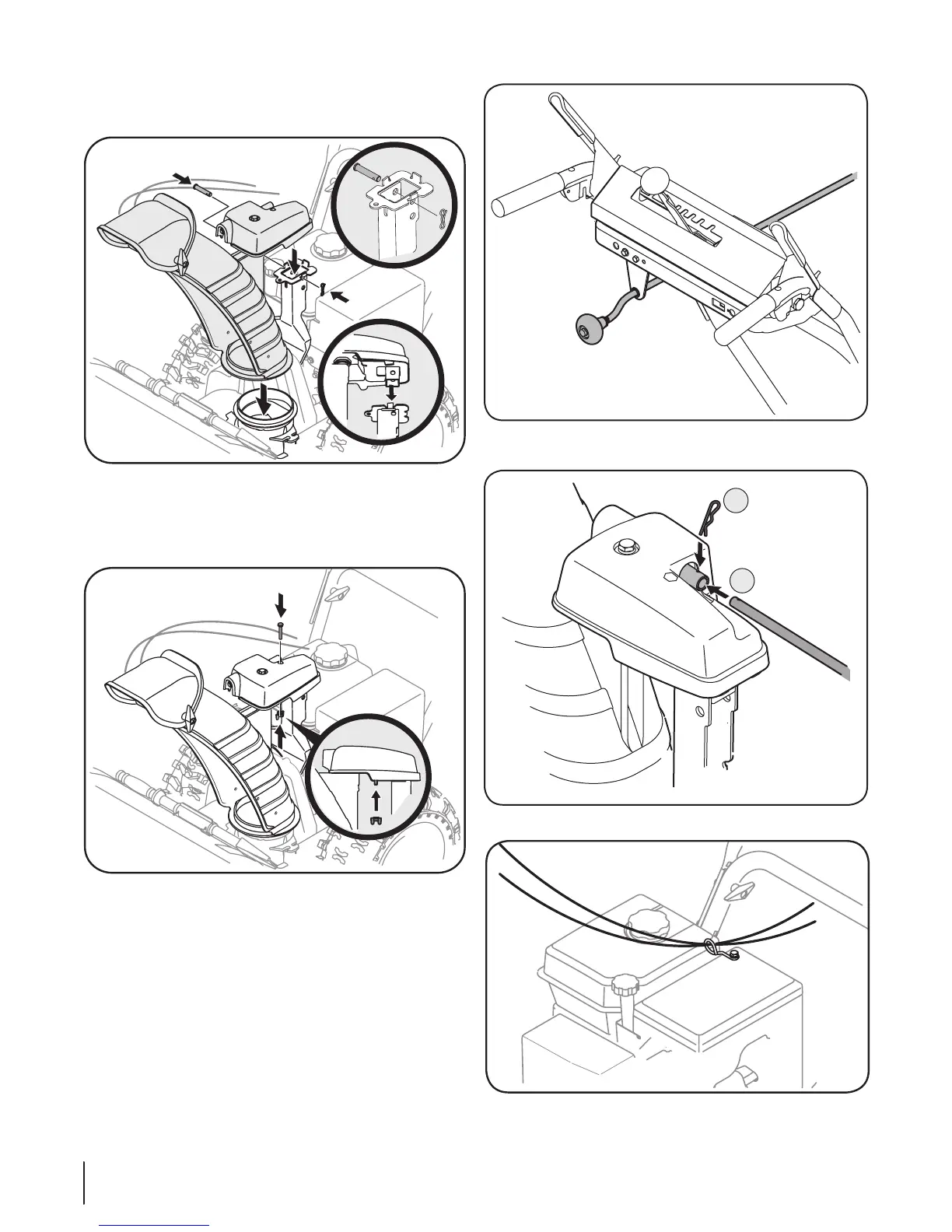
Remove the cotter pin and insert the chute crank rod a.
into the connector on the chute control assembly.
See Fig. 3-7.
Align the hole in the chute crank rod with the hole b.
in the connector, secure with cotter pin previously
removed.
Check that all cables are properly routed through the cable •
guide on the right side of the chute crank rod. See Fig. 3-8.
Fig. 3-5
Fig. 3-6
Fig. 3-7
Fig. 3-4
8 SectioN 3— aSSeMbly & Set-up
 Loading...