Shanghai Yatai – NTT-2000(N)
Please read this manual thoroughly for the instruction of correct usage before using this product and keep this manual
as a reference.
l Before cleaning the controller, please ensure that the power is switch off.
l Please remove stains on the display panel by using a soft cloth only.
l No scrubbing or touching the display panel with any hard object, the display panel can be easily scratched.
l Do not press any button on the display panel using pointy objects such as ballpoint pen or screw driver, it can
easily scratch the panel or damage buttons on the panel.
Please confirm the product you received is in full agreement with the model that you selected according to the
following codes:
① Panel size(mm)
D:96×96 E:72×72
F:96×48 (Vertical type)
F(H):(Horizontal type)
G:48×48
② Model:2
③ Control Mode
0:On-Off Control
4:On–Off PID Control (heating Type)
④ Timing Output
0: no timing output
1: Relay Output
2: Buzzer Output (internal)
3: Buzzer Output (external)
⑤ Timer Mode
0: NO timing
1: Timer Startup by a switch and display counting down
2: High and low temperature control, Timer Startup by a short current
and display counting down
3: Timer Startup with set temperature and Counting down
4: Turn switch on to start timer and the relay will be closed. When the
timer reaches the preset value, the relay will be opened.
5: Release switch to start timing, display will show remaining time,
when the timer research preset value, the relay will be closed.
6: Releasing switch to start timing, the relay will be closed, when the
time reaches the preset value, the relay will be opened.
⑥ Output Type
Omit: Relay Output
V: Logic Output (for the control of solid-state relay SSR)
G: SRC ((under 300W only)
WG: external silicon controlled rectifier
WR: external relay
⑦ Thermocouples types:
K:0-800℃;E:0-600℃
⑧ LRL
⑨ URL
2.1 Caution when installing
Please install the controller under the following conditions:
l Temperature: 0 to 50 degrees C.
l Humidity: 45% to 85% RH.
l Atmospheric pressure: 86 to 106kPa
Please avoid the following conditions during installation:
l Rapid temperature changes, leading to dew condensation.
l Corrosive gases (especially sulfide gas, ammonia, etc.) or flammable gases.
l Direct vibration or shock
l Contact with water, oil, chemicals, steam , smoke, or hot water
l High concentrations of atmospheric dust, salt or iron particles
l Large inductive interference, resulting in static electricity, magnetic fields or noise.
l Direct sunlight.
l Radiant heat sources, etc
2.2 Mounting Process
(1)Cut out rectangle holes on the panel for installing the controller according to the required hol
When installing more than one controller, the minimum horizontal and vertical distance between two holes should be
25mm and 30mm respectively.
(3)Insert the controller into the hole on the panel.
(4)Insert mounting bracket in the slot for mounting the controller.
(5)Push the mounting bracket tightly to connect the instrument and the panel firmly.
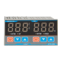
2.3 Panel layout
① PV Display device (Red)
• Display the measuring temperature or according to the
instrument’s state to display the various types of prompt code.
SV Display device (Green)②
• Display the set temperature or according to the instrument’s
state to display the various type of parameters as the timing time
and etc.
Indicator③
• RUN indicator for auto-tuning (Green),Twinkling at
working.
• OUT indicator for heating output (Green), Bright at working.
• TIME indicator for timing (Red), Bright at work
④ , ⑤ Digital Adjustment Key
• Used to modify the setting value and the control parameters,
or for entering in the timing state.
• Used to modify the setting value, calling out, modify and
confirm the parameters。
2.4 Key Performance
1) Measurement accuracy: 0.5%±1dig 2) Power: 220VAC 3)Operation Temperature:0~50℃ 4)Fuzzy PID control
5) This product conforms with the “Q/SQG01-1999 Intelligent Digital Display Adjustor” Standard Regulation.
3.1 Attention to the wiring
(1) For thermocouple input, the corresponding compensation line should be used.
(2) Input signal lines should be far away from power supply and load lines to avoid noise interference.
3.2 Wiring Terminal’s configuration