11
When rigging for overhead lift, attach
shackle bolts to the lifting lugs. Bring the
four individual rigging cables together at a
point high enough that the angle between the
rigging line and the top of the unit is no less
than 60°, as shown in the Figure 4. This will
require cable lengths a minimum of 36” (1m)
for all sizes except the WFC-SC50 which will
require 48” (1.3m) cable length.
There are times when the unit simply
cannot be moved to the final installation site
while remaining in the vertical position. It is
be permissible to lay the unit on its side, so
long as proper precautions and guidelines
are followed.
Figure 5 – Laying the Unit on its Side
1. Transport by vehicle ONLY with the unit in
vertical configuration. THERE IS NO
ALTERNATIVE. Transport by vehicle over
roadway while the unit is not in the vertical
configuration will void the warranty.
2. The unit may ONLY lay onto its back - the side
with the water connections. It may NOT lay on
any other side!
a. While on its back, the water piping acts as
legs to support the internal tubing bundles.
On any other side, the tubing bundles will
not be properly supported and may shift or
become severely damaged, rendering the
machine inoperable.
3. Do not simply tip the unit over onto its back. It
should be lifted and turned to the horizontal
configuration while fully supported and
suspended, though it only need be barely off
the ground while turning.
4. DO NOT lay the unit directly onto the ground
in a manner that will allow the water
connections support the weight of the unit.
Attach 4x4 blocks or timbers to the frame for
support in the horizontal configuration.
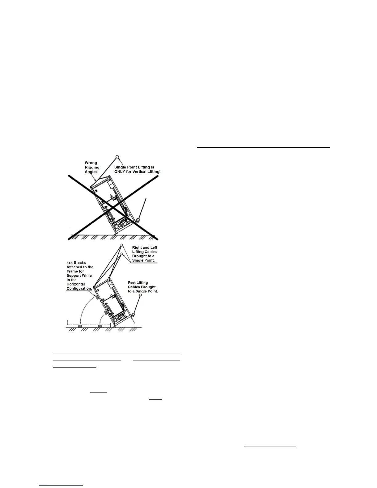
5. DO NOT USE A SINGLE POINT LIFTING
when laying the unit onto its side. At least
THREE lifting points will be necessary.
To properly lay the unit onto its side:
1. Remove all cabinet panels in order to prevent
damage to them.
2. Attach 4x4 blocks or timbers to the rear frame
to act as support feet while the unit is in the
horizontal configuration.
3. Attach two rigging cables to the unit feet
across the front of the unit. Bring these cables
to a single point, maintaining a minimum of
60° between unit and cable.
4. Attach two rigging cables to the left side lifting
lugs. Bring these cables to a single point.
5. Attach two rigging cables to the right side
lifting lugs. Bring these cables to a single
point.
6. Using these three points, lift the unit slightly off
the ground, using the lifting cables on the feet
to rotate the unit onto its back. Use the right
and left side lifting cables to control the
sideways rotation.
7. Once the unit is in the horizontal configuration,
let it gently rest on the blocks that were
attached during step 2.
8. Once the unit is to be turned back to the
vertical configuration, it is preferable that the
unit again be lifted and rotated in the same
manner as described above. However, in
cases where mechanical lifting is not available
at the installation site, the unit CAN tilted over
onto its feet.
Do not let the unit fall hard onto its feet.
Do not allow the feet to become deformed.
Be mindful of the considerable mass of
the unit (refer to the Specifications page).
Using human power alone to tip the unit is
not advised as it could become a very
dangerous and potentially deadly procedure.
 Loading...