EasyManua.ls Logo

YOKOGAWA Daqstation DX2020 User Manual

YOKOGAWA Daqstation DX2020
366 pages
To Next Page IconTo Next Page
To Previous Page IconTo Previous Page
Page #195 background imageLoading...
Page #195 background image
5-15
IM 04L42B01-01E
Operations for Changing the Displayed Contents
1
2
3
4
5
6
7
8
9
10
11
12
13
App
Index
Note
• Ifthescalesofmultiplechannelsaresettothesameposition,thescaleofthechannel
assigned first to the group is displayed.
Example: If the order of assignment of a group is 003.002.001, and the scale display
position of all channels is set to 1, the scale of channel 3 is displayed at display position 1.
• Evenifsomeofthescaledisplaypositionsareskipped,thescaleispackedtowardsdisplay
position 1.
Example: Suppose the assignment of channels to a group is 001.002.003, and the display
positions of the scales are set to 1, 3, and 6, respectively. The scales are actually displayed
at positions 1, 2, and 3, respectively.
• Thescaleisdividedinto4to12sectionsbythemainscalemarks.Thesectionbetween
the main scale marks is divided into 5 or 10 subsections by medium and small scale marks.
However, small scale marks are not displayed in the following cases.
• Whentheresolutionoftheinputrangeissmallerthanthetotalnumberofsmallscale
marks.
• Whenzonedisplayisused.
• Whenpartialexpandeddisplayisused(numbersaredisplayedattheendsofthescale
and at the boundary position).
• Thescalevaluesaredisplayedaccordingtothefollowingrules.
• Ifthenumberofscaledivisionsis4to7fortheverticaltrenddisplay,valuesare
displayed at all main scale marks. If the number of scale divisions is greater, the values
are displayed at every other main scale marks.
• Scaleupperandlowerlimitsaredisplayedattheendsofthescale.
• Scalevaluesaredisplayedupto3digitsexcludingtheminussign.However,ifthe
integer part of values at the ends of the scale is both 1 digit or the integer part is zero, 2
digits are displayed.
Example: If the scale is –0.05 to 0.50, the lower limit is “–0.0” and the upper limit is “0.5.”
• Iftheintegerpartofeitherendofthescaleis2or3digits,thefractionalpartistruncated.
Example: If the scale is 0.1 to 100.0, the lower limit is “0” and the upper limit is “100.”
• Iftheintegerpartofeitherendofthescaleis4ormoredigits,thevalueisdisplayed
using a 3-digit mantissa and exponent like “×10” or “×10
2
”.
Example: If the scale is 10 to 2000, the lower limit is “1” and the upper limit is “200 × 10”.
• Theunitisdisplayednearthecenterofthescale.Ifpartialexpandeddisplayisused,
the display position is offset from the center. For the vertical trend display, the number of
characters that can be displayed is up to six. For the horizontal trend display, the number of
characters that can be displayed is up to four.
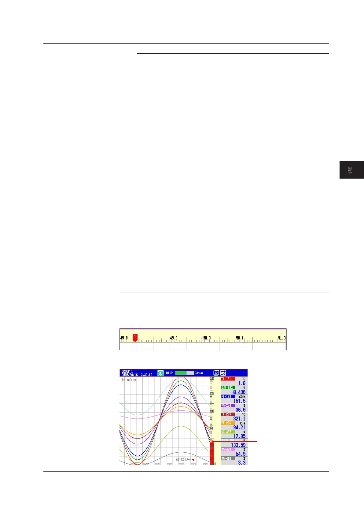
• Trend>Scale>Digit
Fine: For example, if the scale range is “49.0 to 51.0” and you select “Normal,” the
scale values are displayed using 2 digits (“49” for example, see Note above). If you
select “Fine,” the scale values are displayed using 3 digits as shown below.
• Trend>Scale>Value indicator
The current value is displayed as a mark or a bar graph.
Bar graph
5.7DisplayingaScaleontheTrendDisplay

Table of Contents

Question and Answer IconNeed help?

Do you have a question about the YOKOGAWA Daqstation DX2020 and is the answer not in the manual?

YOKOGAWA Daqstation DX2020 Specifications

General IconGeneral
BrandYOKOGAWA
ModelDaqstation DX2020
CategoryRecording Equipment
LanguageEnglish

Summary

Chapter 1 Overview of Functions

1.1 Input Section

Describes measurement channels, scan interval, and A/D converter integration time.

1.2 Alarms

Explains the alarm types, hysteresis, and delay functions.

1.4 Data Storage Function

Explains the types of data that the DX can record and how to store them.

1.6 Event Action and Remote Control Functions (/R1 and /PM1 Options)

Describes how specified actions are carried out when events occur.

1.7 Security Function

Explains the DX security functions, including key lock and login.

1.8 Computation and Report Function (/M1 and /PM1 Options)

Explains how to define equations in computation channels.

Chapter 3 Measurement Channels and Alarms

3.1 Setting the Scan Interval and the Integration Time of the A/D Converter

Selects the scan interval and A/D converter integration time.

3.3 Setting the Input Range

Sets the input range for each channel.

3.7 Setting Alarms on Channels

Sets alarms after setting the range for each channel.

3.9 Performing Calibration Correction (/CC1 Option)

Corrects input values using segments for measured values.

Chapter 4 Switching Operation Screens

4.2 Displaying the Measured Data as Waveforms, Values, or Bar Graphs

Explains how to use trend, digital, and bar graph displays.

4.3 Displaying Past Measured Data (Historical Trend Display)

Describes five methods to display past measured data.

Chapter 6 Saving and Loading Data

6.1 Setting the Recording Conditions of the Measured Data

Sets the method for recording measured data.

6.2 Setting the Method for Saving the Data

Sets the method for recording data to the storage medium.

6.9 Saving/Loading the Setup Data

Saves setup data to external storage or loads it from external storage.

Chapter 7 Customizing Actions Using the Event Action and Remote Control Functions (/R1 and /PM1 Options)

Chapter 8 Using the Security Function

8.1 Disabling the Key Operation (Key Lock Function)

Disables key operations by locking the keys.

8.2 Enabling Only Registered Users to Operate the DX (Login Function)

Allows only registered users to operate the DX.

Chapter 9 Computation and Report Functions (/M1 and /PM1 Options)

9.1 Setting the Expression, Measurement Range, Alarm, Tag, and Data Storage on Computation Channels

Sets computation channel expressions, ranges, alarms, tags, and data storage.

9.2 Writing Expressions

Explains the meaning and how to write expressions.

9.5 Creating Reports

Sets how the reports are created.

Chapter 10 Using External Input Channels (/MC1 Option)

10.1 Setting External Input Channels

Sets external input channels for external instruments.

Chapter 11 Troubleshooting

11.1 A List of Messages

Lists possible error codes and messages displayed during operation.

11.2 Troubleshooting

Provides a flowchart for troubleshooting common issues.

Chapter 12 Calibration

12.2 Calibrating the DX

Recommends annual calibration for measurement accuracy.

Chapter 13 Specifications

13.3 Data Saving Function

Details internal memory, external storage, and data formats.

Related product manuals