2.HardwareSpecications
2-9
TI 30A10A30-01E
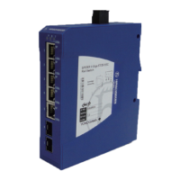
Device status LEDs
Four device status LED functions are as shown below.
Table DevicestatusLEDfunction(MAR1040Family)
LED name Reaction Device status
P (Power)
ON (Green) Normal operation (*1)
ON (Yellow) P1 or P2 power fail
OFF All power fail
FAULT
ON (Red) Detect device status error (*2)
OFF Normal operation
RM (Ring Manager) (*3)
ON (Green) Ring normal
ON (Yellow) Ring error
OFF Ring function not active
Flash During ACA accessing
Sb (Stand by)
OFF Normal (Stand-by mode not enabled)
Flash During ACA accessing
*1: As for a single power model, the Power LED glows in green (Normal) or OFF (Fail).
*2: FAULT LED glows in red when FAULT output pins become open. (The default status as delivered from the factory.)
*3: These LEDs become functional when using ring network technology supported by the network switch vender.
USBinterface
An ACA is connected with the Recommended Switch via USB interface.
V.24 interface
V.24 interface connects a computer with a terminal cable.
RJ-45port
RJ-45 port connects Vnet/IP stations or equipment with UTP cable.
Each port (Port 1 to 16) is dual purpose (RJ45/SFP) combo port.
The combo port will select SFP interface automatically when the SFP module is installed.
As for L3SW, each port has been assigned to an appropriate IP address by default for easy
Vnet/IP inter-domain connection.
Each of the L3SW’s port is used for a connection to each of the Vnet/IP domain respectively.
In case of Vnet/IP communication between domain 1 and 2, connect a port of each L2SW in
Vnet/IP domain 1 and domain 2 to port 1 and port 2 of L3SW.
Dec. 26, 2016-00
 Loading...