7
IM 12D07K04-01EN-P
2.2 INSTALLATION OF ISC40 SENSOR IN ISC40FF
Installation of the ow ttings involves two steps:
• Installation of the sensor
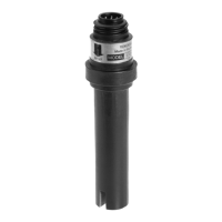
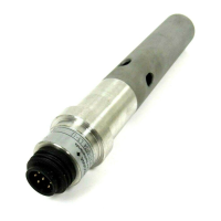
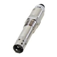
The sensor has to be mounted in the ow tting. It is important that the position of
the sensor in the tting allows easy ow through the hole of the sensor donut (refer
to Section 3 of ISC40 manual). Generally good ow is assured if the ats of the sensor
are oriented perpendicular to the outlet piping. It is also important that the sample
piping is oriented in such a way that the direction of the ow is upwards to assure
complete lling of the ow chamber
• Installation of the tting on wall, railing or stanchion
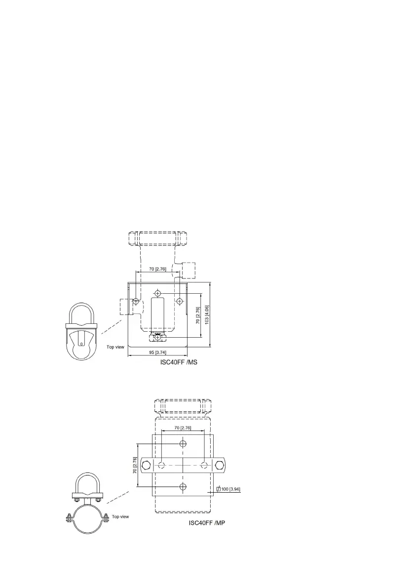
For this purpose, the ow tting has an optional pipe/wall mounting kit /MS or /MP
(see Figure 1 and Figure 2 for details). This kit consists of a clamp ring with bolts and
nuts which clamps around the ow chamber. Therefore, the ow chamber can be
turned in the mounting assembly allowing more exibility in installation. The mount-
ing plate can be mounted on a wall or panel with 2-4 anchor bolts with a diameter
of 10 mm (3/8”) max. For those installations where pipe mounting is requested (2”
nominal pipe), either horizontal or vertical, a saddle and U-bolt have to be used.
Figure 1: Pipe/wall mounting kit /MS
Figure 2: Pipe/wall mounting kit /MP


 To Next Page