Store this manual in an easily accessible place
for quick reference.
User's
Manual
2nd Edition: October 2017 (YMI)
All Rights Reserved. Copyright ©
2015, Yokogawa Meters & Instruments Corporation,
2017, Yokogawa Test & Measurement Corporation
A3
Printed in China
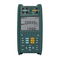
9. Display Functions
Lit when the measured insulation
resistance is being held.
Flashes when the battery voltage is low.
Lit when the rating setting is
1000 V/2000 MΩ.
Lit when the rating setting is
500 V/2000 MΩ
Lit when the rating setting is
250 V/200 MΩ.
Lit when the rating setting is
125 V/200 MΩ.
Indicates overrange (OL).
Indicates the extension bar graph.
Change toward smaller values
Change toward larger values
Stable
Sub-display
Indicates:
• Comparator setting value or
the storage number; or
• The storage number for memory.
Indicates the unit for
insulation resistance for comparator.
Lit when:
• Pressing the MEAS key in
insulation resistance measurement; and
• Residual electrical charges are present
during discharging.
Lit when the comparator is activated.
Lit when the measured
insulation resistance is lower than
the comparator setting value.
Lit when the memory feature is in use.
Indicates the unit for
AC voltage measurement.
Indicates the unit for insulation resistances.
Indicates the unit for
conductor resistance measurement.
Indicates the continuity mark,
which is lit when the measured
insulation resistance is lower than 40 Ω.
The extension bar graph shows how
the measured value is changing
(trend) as follows:
Note that the number of marks means
the degree of change.
■ Overrange Display Functions
OL Display
The tester displays the OL mark when the measured resistance exceeds
the following values.
Insulation resistance measurement:
For1000Vand500Vratings:2000MΩ
For250Vand125Vratings:200MΩ
Conductorresistancemeasurement:400Ω
Display
The tester displays the mark when the internal calculation exceeds
the following values.
Insulation resistance measurement:
For1000Vand500Vratings:approx.4000MΩ
For250Vand125Vratings:approx.400MΩ
Change to Upper/Lower Ranges
•Toupperrange
When the digital reading exceeds 4000,
the measuring range changes to the next upper range.
•Tolowerrange
When the digital reading falls below 360,
the measuring range changes to the next lower range.
Lower Resolution Display
If the digits below the decimal point are not stable,
they can be automatically omitted to limit the resolution.
10. Before Measurement
1. Safety
•Readthehandlingprecautionsinthismanualcarefully.
•Makesureitissafebeforestartingmeasurement.
2. Battery Voltage Verication
•Makesurethatthebatteryvoltagesarewithinthevalidratings
(i.e. the markisnotashing).
•Ifthebatteriesarelow,replacethemasspeciedinthebatteryreplacement
section of this manual.
As the markindicationdependsontheload(currentconsumption),
check that the
mark does not appear for the largest load
whenshort-circuitingtheearthprobeandthelineprobe(0MΩ).
3. Connecting the Probes
•Removetheprobesfromthemeasuredobjectbeforeattaching/detaching
theprobesto/fromthetester.
•MakesuretheMEASkeyisoffwhenattaching/detachingtheprobesto/fromthetester.
•Plugtheearthprobeintotheearthterminal.
•Plugthelineprobeintothelineterminal.
4. Function Switch Verication
Besuretoconrmthatthefunctionswitchissettothedesiredrating.
5. 1000-V Rating
When measuring with the 1000-V rating,
see section 14.1, “Double-action1000-V Function”.
11. Measuring the Insulation Resistance
11.1 Before Connecting the Probes
•Turnoffthepowertothemeasuredobjectbeforeconnectingor
measuring insulation resistance.
•Electricalchargesmaybepresentinthecablesattachedtoormetalof
the electrical equipment being tested. Verify that the equipment is free from
electrical charges before connecting the testing terminals.
•Besuretoconrmthatthefunctionswitchissettothedesiredrating.
ON
OFF
125 V/200 MΩ
250 V/200 MΩ
500 V/2000 MΩ
1000 V/2000 MΩ
Measurement wiring
Insulation resistance ratings:
Power supply side
(primary)
Load side
(secondary)
Set the switch to OFF
Line probe
Earth probe
11.2. Setting the Function Switch
Turn the function switch to the desired measurement rating position.
Theinitialdisplayis“----MΩ”.
11.3 Connecting the Earth Probe
•Ifthemeasuredobjectisgrounded,connecttheearthprobeclipto
themeasuredobject’sgroundline.
•Ifthemeasuredobjectisnotgrounded,thisprocessmaybeomitted.
11.4 Connecting the Line Probe
Bringthelineprobeintocontactwiththemeasuredobject,andthen
press the
key. The display indicates the insulation resistance of
themeasuredobject.
During measurement, exercise care to prevent the leadwire of the line probe from
comingintocontactwiththeground,oororanyotherobject.
Not observing this precaution may result in a failure to measure the correct
insulation resistance.
11.5 After Measurement
•Immediatelyaftermeasurement,electricalchargesresultingfromtheappliedtesting
voltagemayremainpresentintheprobesormeasuredobject.
•Thetester,therefore,isdesignedtoautomaticallybegindischargingelectricityupon
completion of measurement.
VerifythattheALARMLEDturnsoffwhendischargingiscomplete.
12. Measuring AC Voltages
• Do not press the MEAS key while measuring AC voltages.
•Voltagethatexceedsthespeciedlimit(600V)mustnotbeappliedtoterminals.
Doingsocausesalldigitsofthemeasuredvoltagetoashandthebuzzertobeep.
12.1 Setting the Function Switch
Turn the function switch to an AC voltage
measurement (
V)position.
12.2 Connecting the Earth Probe
•Ifthemeasuredobjectisgrounded,connecttheearth
probecliptothemeasuredobject’sgroundline.
•Ifthemeasuredobjectisnotgrounded,
this process may be omitted.
12.3 Connecting the Line Probe
Bringthelineprobeintocontactwiththemeasuredobject.
ThedisplayindicatestheACvoltageofmeasuredobject.
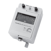
Model MY40
Insulation Resistance Tester
[ Operation Manual ]
Thismanualdescribesthespecicationsandhandlingprecautionsof
the insulation resistans tester.
Before using this product, thoroughly read this manual to understand how to use it properly.
IMMY40-E: Safetyprecautions,componentsandspecicationsetc.
IMMY40-02EN: Operationmanual(thismanual)
ContactinformationofYokogawaofcesworldwideisprovidedonthefollowingsheet.
PIM113-01Z2: Inquiries Listofworldwidecontacts
IMMY40-02EN
2ndEdition:Oct.2017(YMI)