3. Intrinsic Safety Explosion Protection Instrumentation
3-11
TI 32S01J30-01E
Apr. 25, 2022-00
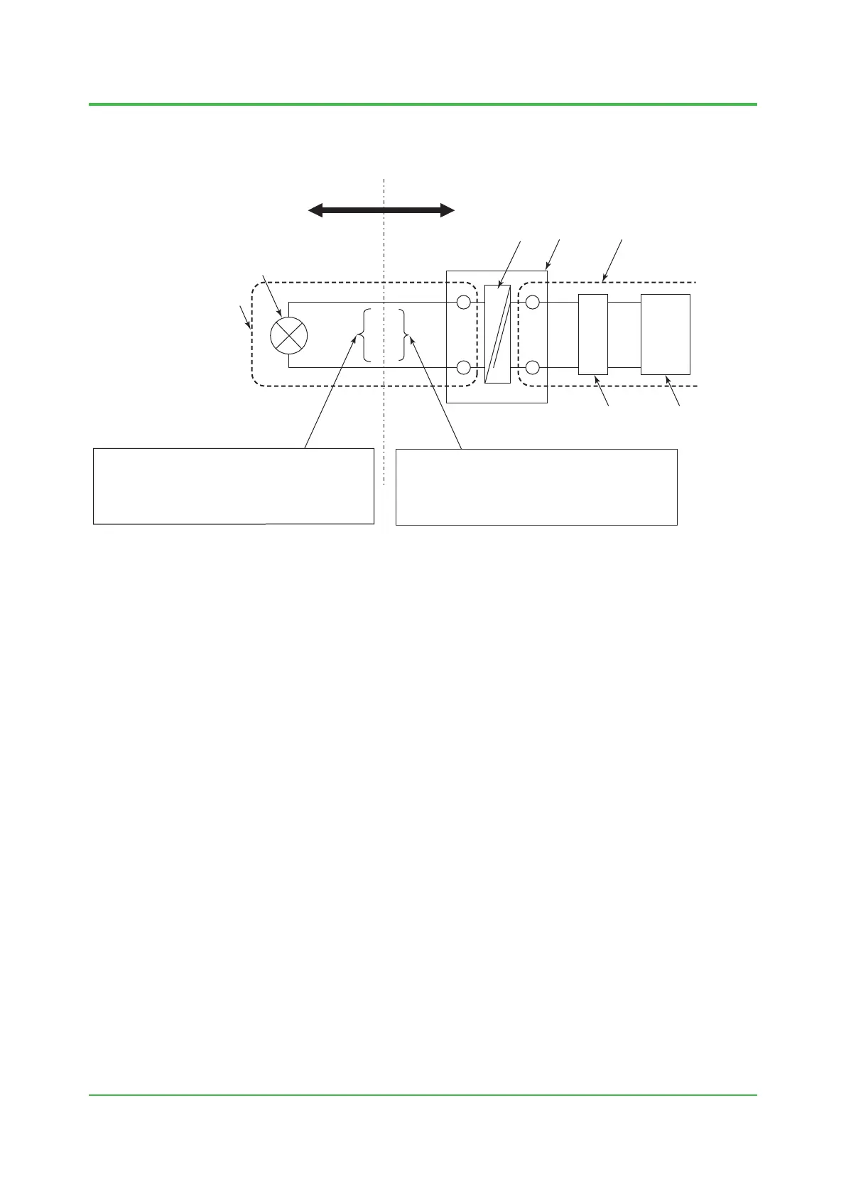
Intrinsic safety circuit should consist of barriers to meet these conditions of permissible voltage,
current, and electricity, and should be wired so that inductance and capacitance of its wiring
doesn’t exceed its permissible value.
Device that gives energy
(The source energy)
Device that receives energy
(The load device)
Intrinsic safety circuit
Intrinsic safety equipment
Non-intrinsic safety circuitBarrierPart for security
Uo:
Io:
Po:
Lo:
Co:
Maximum voltage of intrinsic safety circuit
Maximum current of intrinsic safety circuit
Maximum electricity of intrinsic safety circuit
Permissible inductance of intrinsic safety circuit
Permissible capacitance of intrinsic safety circuit
Ui:
Ii:
Pi:
Li:
Ci:
Permissible voltage of intrinsic safety circuit
Permissible current of intrinsic safety circuit
Permissible electricity of intrinsic safety circuit
Internal inductance
Internal capacitance
Controller,
indicator,
recorder
Input/
output
module
F030201.ai
Figure Composition Used in a Barrier
 Loading...