Yokogawa Electric Corporation
Model
ProSafe-RS/ProSafe-RS Lite
Title
Control drawing
No.
NFM014-A13
Page
4
Revision
78
(continued)
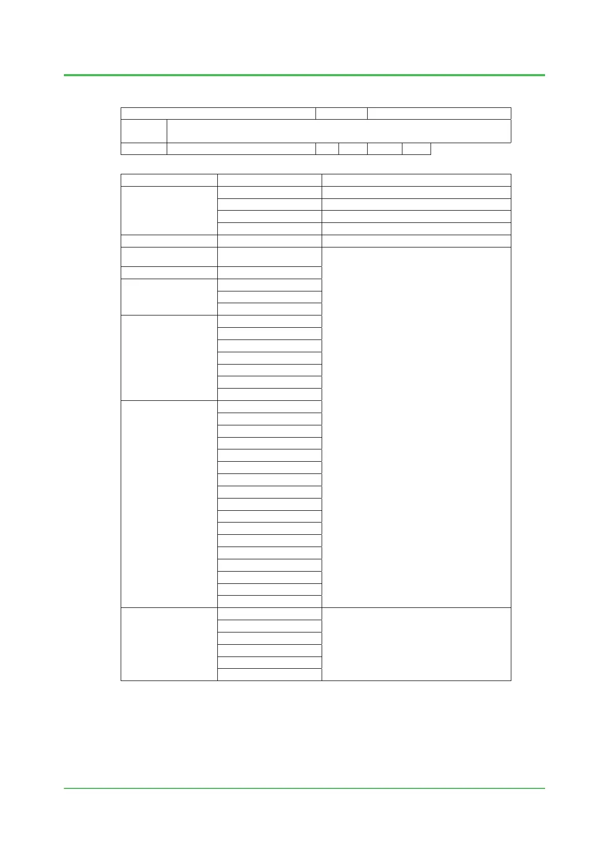
Classifications
Model
Ambient Temperature (*1)
Safety Control Units
for Vnet/IP
L1SC70S-SA1
□110
−20 to 40 °C (*2)
L1SC70S-FA1□110
−20 to 70 °C (*3)
L1SC70D-SA1□110 −20 to 40 °C (*2)
L1SC70D-FA1□110
−20 to 70 °C (*3)
Safety Node Units
L1NB10D-4
□E
−20 to 70 °C (*3)
Unit for Optical Bus
Repeater Module
L1NT10D-2
□E
−20 to 70 °C
Processor module
L1CP471-11
Power supply module
L1PW481-E3
L1PW482-E3
L1PW484-E3
Bus interface module
L1SB401-E3
L1EC401-E1
L1EC402-E1
L1NT401-EF
L1NT501-EF
L1NT411-EF
L1NT511-EF
I/O module
L1AI143-
□E□
L1AI143-□F□
L1AV144-SE3
L1AV144-SF3
L1AI533-HE3
L1AI533-HF3
L1AT145-SF3
L1AR145-SF3
L1DV144-SE□
L1DV144-SF□
L1DV531-LE□
L1DV531-LF□
L1DV541-SE□
L1DV541-SF□
L1DV521-SF□
L1DV53A-SF3
L1DCV01
Terminal block
L1TA4S-
□0
−20 to 70 °C
L1TA4D-□0
L1TB4S-□0
L1TB4D-□0
L1CCC01
L1CCC02
*1 The ambient temperature ranges are specified for the temperature around Field Control Unit,
Base Plate or Terminal Board, and not for the temperature around each model.
*2 0 to 40 °C when ALR111-S
□1, ALR121-S□1 or ALE111-S□1 is installed.
*3 0 to 60 °C when ALR111-S
□1, ALR121-S□1 or ALE111-S□1 is installed.
Dec. 3, 2021-00
 Loading...