Yokogawa Electric Corporation
Model
ProSafe-RS N-IO
Title
Control drawing
No.
NIE009-A101
Page
3
Revision
15
(Continued)
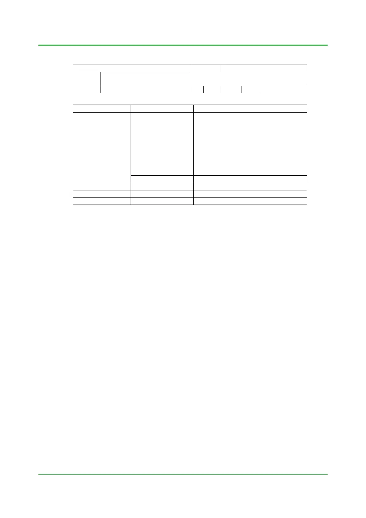
Classifications
Model
Ambient Temperature (*1)
I/O module
S2MMM843-SS1130
S2MDV843-0S1130
−40 to 70 °C (*4)
When utilizing Digital output function, the total
load current of all channels is limited as
shown below according to the derating
specifications due to the ambient temperature
of modules.
−40 to 40 °C: Max. 10.56 A
40 to 50 °C: Max.9.71 A
50 to 60 °C: Max.8.85 A
60 to 70 °C: Max.8 A
S2DCV02-0
−40 to 70 °C (*4)
Terminal board
A2BM4-130
−40 to 70 °C (*5)
Power Cable S2KPB10-C□□□ −40 to 70 °C (*4)
Bus cable
S2KLF10-1
□□2
−40 to 70 °C (*4)
*1 The ambient temperature ranges are specified for the temperature around Field Control Unit,
Base Plate or Terminal Board, and not for the temperature around each model.
*2 0 to 40 ° C when ALR111-S
□1, ALR121-S□1 or ALE111-S□1 is installed.
*3 0 to 60 ° C when ALR111-S
□1, ALR121-S□1 or ALE111-S□1 is installed.
*4 If it is mounted on S2BN1D-
□9130, the minimum temperature is limited to −20 °C for using
AKB331 or AKB651 together.
*5 The minimum temperature is limited to −20 °C for using AKB331 or AKB651 together.
Dec. 3, 2021-00
 Loading...