IM 05C01E12-41E
9
6. HARDWARE SPECIFICATIONS
•
Input: 1 point
•
Input type: Universal; can be selected by software
•
Input accuracy (at 23 ±2°C ambient temperature)
•
Thermocouple: ±2°C±1digit
However,
• ±4°C for thermocouple input –200 to –100°C
• ±3°C for thermocouple input –100 to 0°C
• ±5°C for type R and S (±9°C for 0 to 500°C)
• ±9°C for type B (accuracy is not guaranteed for 0 to 400°C)
•
RTD: ±1°C±1digit
•
Voltage (mV, V): ±0.3%±1digit
•
Sampling period for measured value input: 500ms
•
Burn-out detection: Functions for thermocouple or RTD input (burn-out upscale
only; cannot be switched off)
•
Input resistance: 1MΩ or greater for thermocouple or DC mV input. Approx. 1MΩ for DC V input
•
Maximum allowable signal source resistance :
250
Ω
for thermocouple or DC mV input
2k
Ω
for DC V input
•
Maximum allowable wiring resistance for RTD input:
10Ω/wire (The resistance values of
three wires must be the same.)
•
Allowable input voltage: ±10V DC for thermocouple or DC mV input
±20V DC for DC V input
•
Noise rejection ratio: Normal mode noise: Min. 40dB
(50/60Hz) Common mode noise: Min. 120dB
(Min. 90dB for DC V input)
•
Error of reference junction compensation: ±1.5°C (at 15-35°C)
±2.0°C (at 0-50°C)
The reference junction compensation cannot be switched off.
•
Applicable standards: Thermocouple and resistance temperature detector
JIS/IEC/DIN (ITS90)
•
Output: 1 point (for standard type) or 2 points (for heating/cooling type)
•
Output type: Choose one from (1) to (3) below:
(1) Relay contact output
Contact capacity: 3A at 240V AC or 3A at 30V DC (with resistance load)
Note: The control output relay cannot be replaced by users.
(2) Voltage pulse output
On voltage: 12-18V DC load resistance: 600Ω or greater
Off voltage: 0.1V DC or less short-circuit current: approx. 30mA
(3) Current output
Output signal: 4 to 20mA
Maximum load resistance: 600Ω
Output accuracy: ±0.3% of span
(at 23±2°C ambient temperature)
Measured Value Input
Alarm Functions
Control Output
The retransmission output is provided only when the /RET option is specified, but is
not available for the heating/cooling type.
•
Output signal: Measured value in 4-20mA DC
•
Maximum load resistance: 600Ω
•
Output accuracy: ±0.3% of span (at 23±2°C ambient temperature)
Retransmission Output
•
Safety: Compliant with IEC/EN61010-1: 2001, approved by CSA1010, approved by
UL508.
Installation category : CAT. II (IEC/EN61010, CSA1010) Pollution degree : 2
(IEC/EN61010, CSA1010)
Measurement category : I (CAT. I : IEC/EN61010)
Rated measurement input voltage : 10V DC max.(across terminals), 300V AC
max.(across ground)
Rated transient overvoltage : 1500V (Note)
Note : It is a value on the safety standard which is assumed by IEC/EN61010-1 in
measurement category I, and is not the value which guarantees an apparatus
performance.
Caution: This equipment has Measurement category I, therefore do not use the
equipment for measurements within measurement categories II, III and IV.
•
EMC standards: Com
lies with EN61326.
The instrument continues to operate at a measurin
accurac
of within
2
of the
range during tests.
Safety and EMC Standards
The communication function is provided only when the /RS option is specified. (For details, read the
user’s manual of the communications function IM 05C01E12-10E.)
■Communication Protocol
•
Personal computer link: Used for communication with a personal computer, or UT
link module of the FA-M3 controller (from Yokogawa Electric Corporation).
•
Ladder communication: Used for communication with a ladder communication
module of the FA-M3, or a programmable controller of other manufacturers.
•
MODBUS communication: Used for communication with equipment featuring the MODBUS protocol.
■Communication Interface
•
Applicable standards: Complies with EIA RS-485
•
Number of controllers that can be connected: Up to 31
•
Maximum communication distance: 1,200m
•
Communication method: Two-wire half-duplex, start-stop synchronization, non-procedural
•
Communication speed: 2400, 4800, or 9600 bps
Communication Function
■
Alarm Functions (Option Code /AL or /HBA)
•
Alarm types: 22 types (waiting action can be set by software):
PV high limit, PV low limit, Deviation high limit, Deviation low limit, De-energized
on deviation high limit, De-energized on deviation low limit, Deviation high and low
limits, High and low limits within deviation, De-energized on PV high limit, De-
energized on PV low limit, Fault diagnosis output, FAIL output
•
Alarm output: 2 relay contacts
Relay contact capacity: 1A at 240V AC or 1A at 30V DC (with resistance load)
Note: The alarm output relays cannot be replaced by users.
■Heater Disconnection Alarm (Option Code /HBA)
The heater disconnection alarm is available when time-proportional PID control or
on/off control is selected.
•
Heater current setting range: 1 to 80A
•
Alarm output: 1 relay contact (The terminals are the same as those of the /AL option.)
•
On time of burn-out detection: Min. 0.2 second
•
Sensor: CTL-6-S-H or CTL-12-S36-8 (URD Co., Ltd.)
To be purchased separately.
■Timer Function (Option Code /EX/AL or /EX/HBA)
The output contact status changes when the preset time has passed since external contact (TMR)
turned on.
The contact action can be selected by software from:
(1) Make contact–the contact closes upon time-up.
(2) Break–the contact opens upon time-up.
•
Input contact type: See Contact Inputs below.
Contact Inputs
The contact inputs are provided only when the /EX option is specified.
•
Functions: (1) Switching over two setpoints (SP1 and SP2)
(2) Starting a timer (See the Alarm Functions .)
(3) RUN/STOP switching
Can be selected by parameter DIS.
•
Input: 2 points (with the shared common terminal)
•
Input type: Non-voltage contact or transistor contact input
•
Contact capacity: At least 12V/10mA
•
On/off judgment: On state for 1kΩ or less; off state for 20kΩ or greater
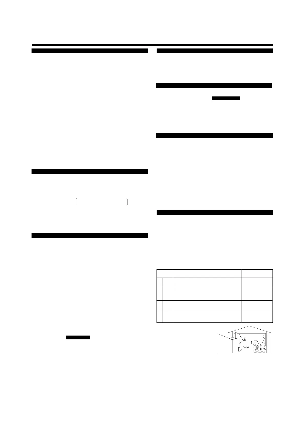
Internal Wirin
Entr
n
abl
1
2
3
4
Measurement
category
CAT.1
CAT.2
CAT.3
CAT.4
Remarks
Appliances,
portable equipments,
etc.
Distribution board,
circuit breaker, etc.
Overhead wire,
cable s
stems,
t
Description
For measurements performed on
circuits not directly connected to MAINS.
For measurements performed on
circuits directly connected to the
low voltage installation.
For measurements performed in
the building installation.
For measurements performed at
the source of the low-volta
e installation

 Loading...
