IM 05C01E12-41E
5
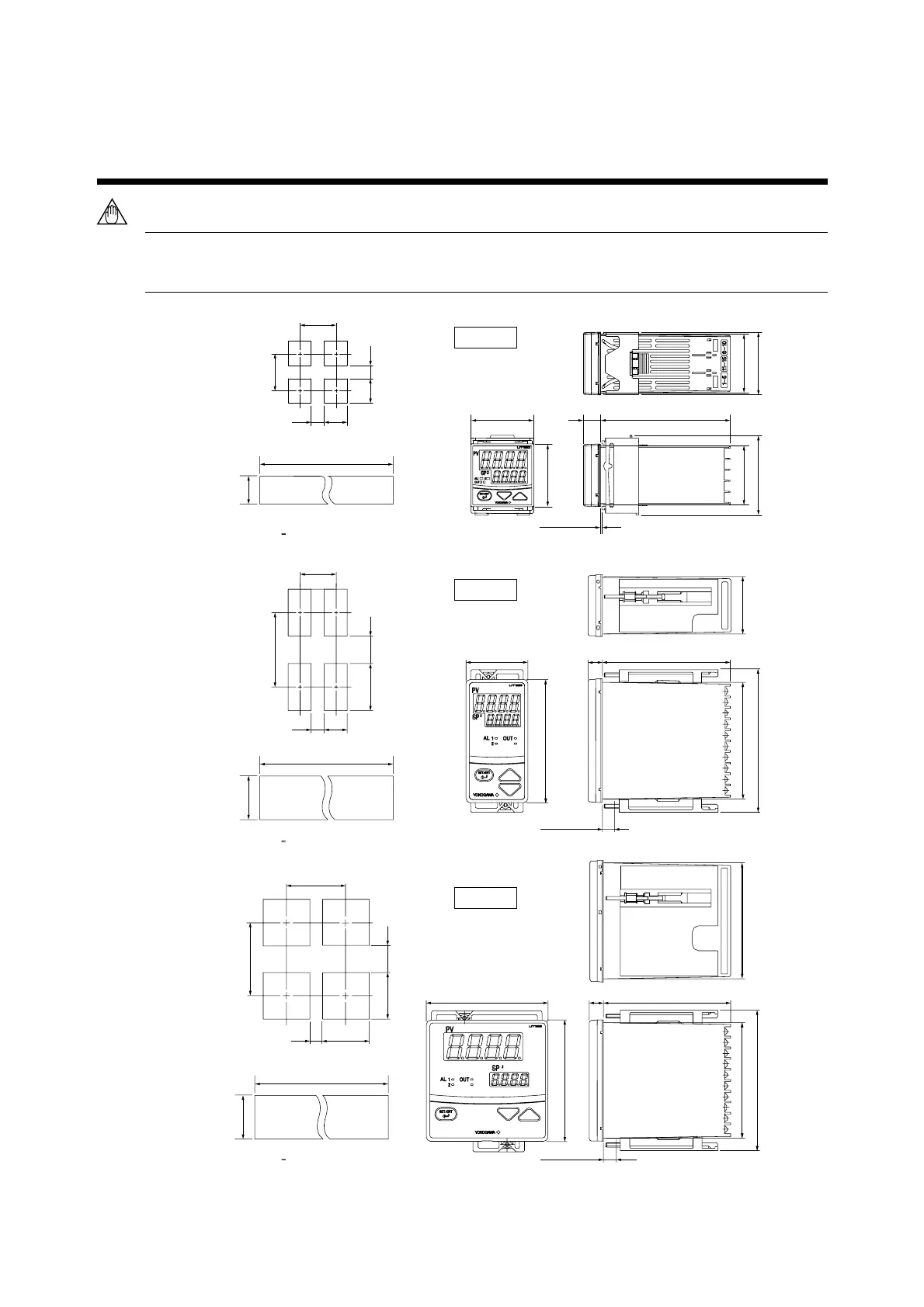
4. PANEL CUTOUT DIMENSIONS AND
EXTERNAL DIMENSIONS
NOTE
Splash-proof construction is not available when the side-by-side close mounting method shown in the
following figures, is chosen for any of the controllers.
max. 91.8
96
1-1051-6041-5031-4021-3011-20
min. 117
min. 145
92
+ 0.8
0
92
+ 0.8
0
25
53
+0.8
0
92
2. Side-by-side Close Mounting
1. General Mounting
96
11
100
max. 91.8
max. 112
Panel thickness
1 to 10
Unit: mm
UT155
N is the number of controllers.
If N
>
5, then measure the actual length.
[(N–1)
×96+92]
+0.8
0
1-1021-301-20
min. 70
48
min. 145
92
+0.8
0
45
+0.6
0
max. 44.6max. 91.8
max. 112
100
96
Panel thickness
1 to 10
11
25
53
+0.8
0
92
2. Side-by-side Close Mounting
1. General Mounting
Unit: mm
UT152
N is the number of controllers.
If N
>
5, then measure the actual length.
[(N–1)
×48+45]
+0.6
0
max. 61
Panel thickness
max. 47.8
max. 44.8
max. 44.8
10012
48
48
1 to 10
Unit: mm
UT150
1. General Mounting
min. 70
min. 70
45
+0.6
0
45
+0.6
0
25
25
[(N–1)×48+45]
+0.6
0
+0.6
0
45
2. Side-by-side Close Mounting
N is the number of controllers.
If N
>
5, then measure the actual length.

 Loading...
