13-1
IM WT3001E-51EN
Cycle-by-Cycle Measurement
13
13.1 Cycle-by-Cycle Measurement Function
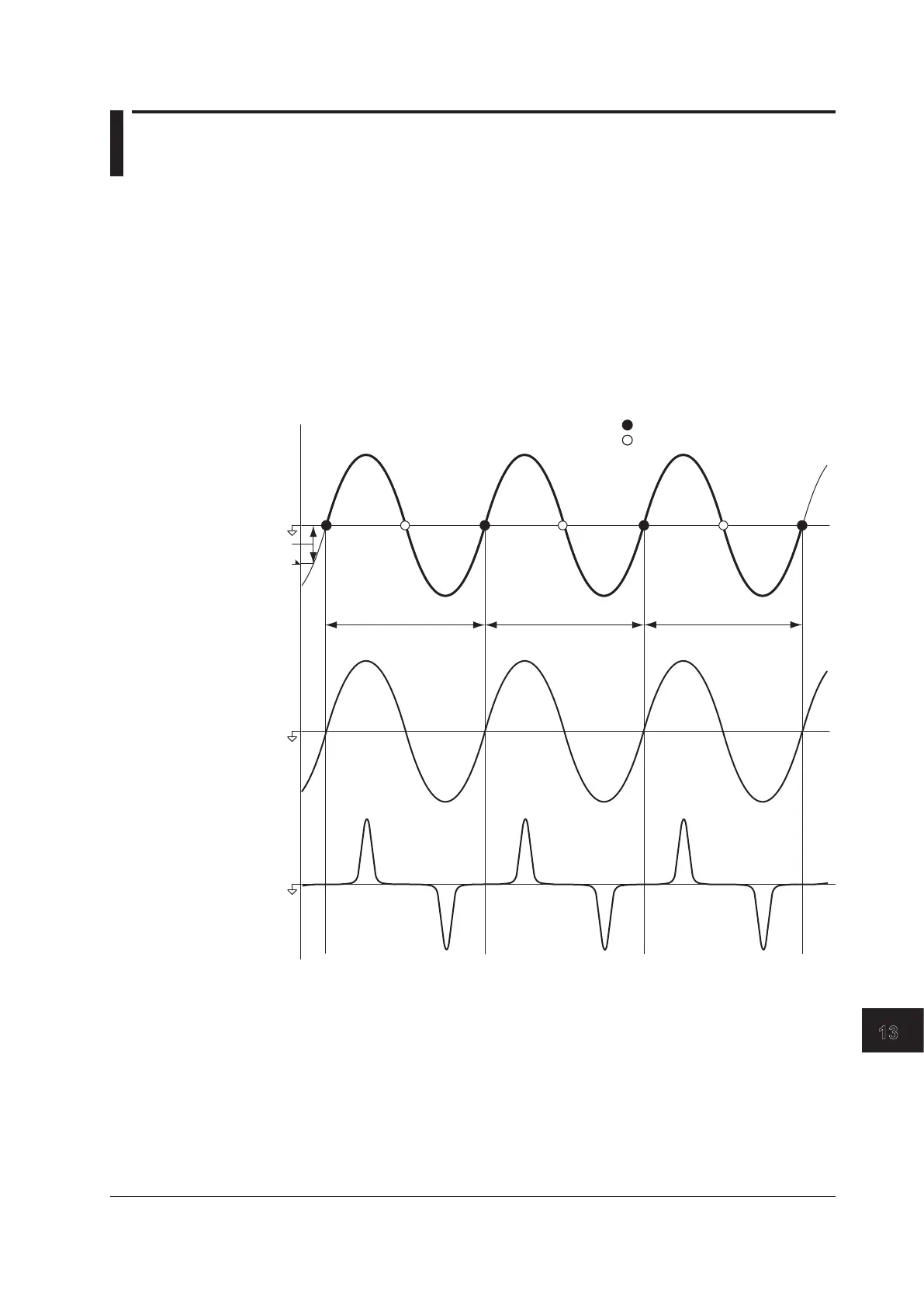
Cycle-by-cycle measurement is a method by which the voltage, current, power, and other
parameters are calculated for each cycle of the AC input signal with respect to the zero-
crossing of the synchronization source signal. When the measurement of the specified
frequency is complete, the measured values are listed in order by period.
The figure below shows the measurement periods when the measurement conditions of
the cycle-by-cycle measurement are set as follows:
Synchronization source: U1
Synchronization source slope: Rising
Measurement cycle count: 3 (The minimum value you can actually specify is 10.)
Synchronization
source U1
Current Input I1
Trigger level
Trigger
Zero crossing (rising slope)
Zero crossing (falling slope)
Measurement Period Measurement Period
Measurement Period
• Types of Measurement Functions
The following measurement functions are measured for each measurement element
and wiring unit.
Freq: Synchronization source frequency
U: Voltage
*1
I: Current
*1
P: Active power S: Apparent power
Q:Reactivepower λ:Powerfactor
Speed Torque
Pm: Mechanical power
*1 RMS, MEAN, DC, or RMEAN value depending on the voltage or current mode setting.
Chapter 13 Cycle-by-Cycle Measurement

 Loading...


