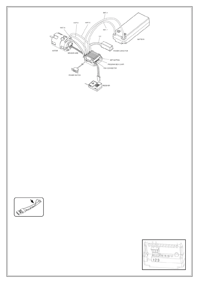
5.Connection
■ Caution
For maximum performance, black silicon wire without any connector was used for provided 12AWG wire. For soldering
the battery and motor wires onto the solder bar, we recommend the soldering iron with at least 60W, and try to avoid
soldering more than 5 seconds. Overheat can damage the ESC. With provided tube, it is possible to prevent the short
circuit and to check the polarity after connection.
■ Motor wire connection
When connecting ESC and motor, the wire A/B/C should go to where they belong. However, some cars have their
wirings in opposite way. For this case, you can switch from A-B-C to C-B-A on Motor-Wiring setting. If changed it to C-B-A,
then the C & A should be switched on the fi gure above, and incorrect setting and connection can cause a critical
problem. For your information, if the ESC is reset, then the C-B-A wiring setting will be back to A-B-C, so switch it to C-B-A
again and then use. Then connect the sensor wire to 6-pin sensor port.
■ Power capacitor
Do not ever drive without power capacitor. This is absolutely needed to protect the ESC and improve the punch. Proper
polarity is very signifi cant. Connect indicated red wire in the fi gure above to (+) of the ESC. Connect another wire to (-)
of the ESC, and the connected wire should be short. Incorrect connection and poor soldering will damage the ESC. The
warranty does not cover this part.
■ Battery wire connection
Proper polarity is very signifi cant. Make sure if (+) wire is connected to (+) of the battery, and vice versa for (-) wire. If
connection is not adequate, then it will surely damage the ESC. The warranty does not cover this part.
■ Receiver wire connection
Throttle wire of the ESC should be connected to 2CH of the receiver, and the white indication of the wire is the signal.
This wire supplies 6/7.4V voltage to receiver and servo and others, therefore, there is no need of additional battery
connected to receiver. If external power is connected to the receiver, the ESC might get damaged.
Note!
If you want to use a separate battery for the receiver, not using the ESC power, the middle wire(+)
of the BEC plug should be disconnected as shown in the fi gure. This will prevent reverse current to
the ESC. Otherwise the ESC can be burned by overheating.
■ Power switch box
To power on/off the ESC, you can use the Power Switch Box by connecting it to the connector on the side of the ESC.
Without using it, the ESC will be powered on immediately when the battery is connected.
■ Fan connector
A cooling fan, screws and fan protector are provided according to the ESC
specifi cation. The fan mount is located on top of the heat sink, and it is recommended
to use fan under the extreme situation such as modifi ed or 4WD off-road.
You need to remove the RED connector in the center and then connect to the port 1
to use the battery power. In this case, the fan operates all the time.
 Loading...