EasyManua.ls Logo

YOODA SMART TOUCH 2 User Manual

YOODA SMART TOUCH 2
3 pages
To Next Page IconTo Next Page
Page #1 background imageLoading...
Page #1 background image
In order to fully explore available functions of SMART TOUCH 2 system please take a moment and read this manual before using the device. SMART
TOUCH 2 system is compatible with all YOODA brand devices.
From the top:
SMART TOUCH 2 transmitter system
Seal SMART TOUCH 2 system
Finish elements of the seal for SMART TOUCH 2 system
Transition strip with touch sensor for SMART TOUCH 2 system
1. Range:
up to 35 meters
2. Battery:
1 x CR2430
3. Power supply:
3 V
4. Dimensions of the transmitter:
40 x 65 x 17 mm
6. Transmitting power:
10 mW
7. Operating temperature:
from -20°C to 50°C
8. Protection degree:
IP 55
9. Possibility to program 3 work modes:
a) stop the work motor,
b) stop the work motor and reverse one turn
c) stop and maximum motor reverse to the upper end position
Radio receiver range is a variable value and can differ from declared values depending on conditions in which device
operates. Possible sources of changes in range are building construction, interference caused by other radio transmitters
etc.
System SMART TOUCH 2
www.sukcesgroup.pl
1. General information
1
Question and Answer IconNeed help?

Do you have a question about the YOODA SMART TOUCH 2 and is the answer not in the manual?

YOODA SMART TOUCH 2 Specifications

General IconGeneral
BrandYOODA
ModelSMART TOUCH 2
CategoryRemote Control
LanguageEnglish

Summary

General Information and Specifications

Operating Range

Specifies the maximum operating distance for the transmitter.

Battery Type

Identifies the type of battery used in the transmitter.

Power Supply Voltage

Indicates the voltage required for the transmitter's operation.

Transmitter Dimensions

Provides the physical size specifications of the transmitter.

Transmitting Power

States the output power of the radio signal from the transmitter.

Operating Temperature Range

Defines the range of ambient temperatures for safe operation.

Protection Degree (IP Rating)

Details the Ingress Protection (IP) rating for dust and water resistance.

Programmable Work Modes

Outlines the three distinct operational modes that can be programmed.

Installation Procedures

Seal Placement

Instructions for placing the seal at the bottom of the roller slat.

Finish Elements Installation

Instructions for putting finish elements on the seal ends.

Transmitter Seal Connection

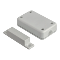
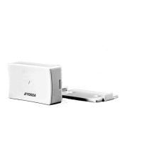
Connecting the finish element of the seal to the transmitter unit.

Limiter Position

Positioning the transmitter limiter parallel to the transmitter.

Selecting Operational Modes

Work Mode A

Stops the motor upon encountering an unexpected obstacle.

Work Mode B

Stops motor and reverses one turn on obstacle detection.

Work Mode C

Stops motor and reverses to upper end position on obstacle detection.

Adding Transmitter to R Type Motors

Programming via A Remote Control

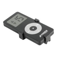
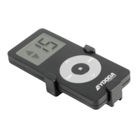
Using button P2 on the A remote to program the transmitter.

Programming via B Transmitter

Using button P2 on the B transmitter to program the transmitter.

Programming Confirmation Actions

Describes the roller shutter and motor actions during programming.

Adding Transmitter via Key-Ring Remote

Simultaneous Button Press

Using STOP and UP buttons simultaneously for programming function.

Programming Confirmation (Key-Ring)

Describes the roller shutter and motor actions during programming.

Related product manuals