Johnson Controls Unitary Products 5121495-UIM-D-0516
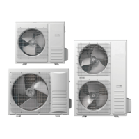
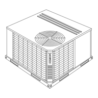
R-410A OUTDOOR SPLIT-SYSTEM
HEAT PUMP
MODELS: 14 SEER -
YHE, TH4, THE, RHP14L SERIES
1.5 TO 5 TONS – 1 & 3 PHASE
INSTALLATION MANUAL
®
LIST OF SECTIONS
GENERAL . . . . . . . . . . . . . . . . . . . . . . . . . . . . . . . . . . . . . . . . . . . . . .1
SAFETY . . . . . . . . . . . . . . . . . . . . . . . . . . . . . . . . . . . . . . . . . . . . . . . .1
UNIT INSTALLATION . . . . . . . . . . . . . . . . . . . . . . . . . . . . . . . . . . . . .2
INDOOR EXPANSION DEVICE . . . . . . . . . . . . . . . . . . . . . . . . . . . . .5
EVACUATION . . . . . . . . . . . . . . . . . . . . . . . . . . . . . . . . . . . . . . . . . . .6
SYSTEM CHARGE . . . . . . . . . . . . . . . . . . . . . . . . . . . . . . . . . . . . . . .6
ELECTRICAL CONNECTIONS . . . . . . . . . . . . . . . . . . . . . . . . . . . . . 7
SYSTEM START-UP . . . . . . . . . . . . . . . . . . . . . . . . . . . . . . . . . . . . . 9
SYSTEM OPERATION . . . . . . . . . . . . . . . . . . . . . . . . . . . . . . . . . . . 10
INSTRUCTING THE OWNER . . . . . . . . . . . . . . . . . . . . . . . . . . . . . 13
WIRING DIAGRAM . . . . . . . . . . . . . . . . . . . . . . . . . . . . . . . . . . . . . 14
START UP SHEET . . . . . . . . . . . . . . . . . . . . . . . . . . . . . . . . . . . . . . 16
LIST OF FIGURES
Typical Installation . . . . . . . . . . . . . . . . . . . . . . . . . . . . . . . . . . . . . . . .3
Installation of Vapor Line . . . . . . . . . . . . . . . . . . . . . . . . . . . . . . . . . . .4
Underground Installation . . . . . . . . . . . . . . . . . . . . . . . . . . . . . . . . . . .4
Heat Protection . . . . . . . . . . . . . . . . . . . . . . . . . . . . . . . . . . . . . . . . . .5
TXV Installation . . . . . . . . . . . . . . . . . . . . . . . . . . . . . . . . . . . . . . . . . .6
TXV Bulb and Equalizer Line Installations . . . . . . . . . . . . . . . . . . . . . .6
Proper Bulb Location . . . . . . . . . . . . . . . . . . . . . . . . . . . . . . . . . . . . . .6
Outdoor Unit Swing Away Control Box . . . . . . . . . . . . . . . . . . . . . . . .8
Outdoor Unit Control Box (Single Phase) . . . . . . . . . . . . . . . . . . . . . . 8
Outdoor Unit Control Box (Three Phase) . . . . . . . . . . . . . . . . . . . . . . 8
Typical Field Wiring (Air Handler / Electrical Heat) (Single-Phase) . . 9
Heat Pump Flow Diagram . . . . . . . . . . . . . . . . . . . . . . . . . . . . . . . . . 10
Demand Defrost Control Module . . . . . . . . . . . . . . . . . . . . . . . . . . . 11
Defrost Operation Curves . . . . . . . . . . . . . . . . . . . . . . . . . . . . . . . . . 12
Wiring Diagram - Single Phase (Demand Defrost) . . . . . . . . . . . . . . 14
LIST OF TABLES
Maximum / Minimum Operating Limit Conditions . . . . . . . . . . . . . . . . .2
R-410A Saturation Properties . . . . . . . . . . . . . . . . . . . . . . . . . . . . . . .7
TEST Input Functionality with Y . . . . . . . . . . . . . . . . . . . . . . . . . . . . .10
TEST Input Functionality without Y . . . . . . . . . . . . . . . . . . . . . . . . . . 10
Status Code Display . . . . . . . . . . . . . . . . . . . . . . . . . . . . . . . . . . . . . 11
Status . . . . . . . . . . . . . . . . . . . . . . . . . . . . . . . . . . . . . . . . . . . . . . . . 11
SECTION I: GENERAL
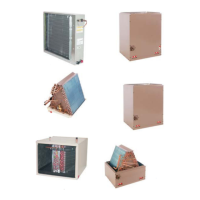
The outdoor units are designed to be connected to a matching indoor
coil with sweat connect lines. Sweat connect units are factory charged
with refrigerant for a nominal sized matching indoor coil plus 15 feet of
field-supplied lines.
Matching indoor coils can be used with a thermostatic expansion valve
(TXV). Refer to the Tabular Data Sheet or to the Technical Guide for
the proper selection.
SECTION II: SAFETY
This is a safety alert symbol. When you see this symbol on
labels or in manuals, be alert to the potential for personal
injury.
Understand and pay particular attention to the signal words DANGER,
WARNING, or CAUTION.
DANGER indicates an imminently hazardous situation, which, if not
avoided, will result in death or serious injury.
WARNING indicates a potentially hazardous situation, which, if not
avoided, could result in death or serious injury.
CAUTION indicates a potentially hazardous situation, which, if not
avoided may result in minor or moderate injury. It is also used to
alert against unsafe practices and hazards involving only property dam-
age.
WARNING
Improper installation may create a condition where the operation of
the product could cause personal injury or property damage.
Improper installation, adjustment, alteration, service or mainte-
nance can cause injury or property damage. Refer to this manual
for assistance or for additional information, consult a qualified con-
tractor, installer or service agency.
CAUTION
This product must be installed in strict compliance with the
enclosed installation instructions and any applicable local, state,
and national codes including, but not limited to building, electrical,
and mechanical codes.
CAUTION
R-410A systems operate at higher pressures than R-22 systems.
Do not use R-22 service equipment or components on R-410A
equipment. Service equipment
Must Be Rated for R-410A.
!
!
!