EasyManua.ls Logo

York D4CG150 User Manual

York D4CG150
20 pages
To Next Page IconTo Next Page
Page #1 background imageLoading...
Page #1 background image
GENERAL
YORK Model DCG units are single package air conditioners
with gas heat designed for outdoor installation on a rooftop or
a slab.
The units are completely assembled on rigid, permanently
attached base rails. All piping, refrigerant charge, and electrical
wiring is factory installed and tested. The units require only
electric power and duct connections at the point of installation.
The gas-fired heaters have aluminized steel tubular heat
exchangers and spark ignition with proven pilot.
INSPECTION
As soon as a unit is received, it should be inspected for possible
damage during transit. If damage is evident, the extent of the
damage should be noted on the carrier’s freight bill. A separate
request for inspection by the carrier’s agent should be made in
writing. Refer to Form 50.15-NM for additional information.
REFERENCE
Additional information on the design, installation, operation and
service of this equipment is available in the following reference
forms:
55.70-N1 - General Installation
55.70-N2 - Pre-start & Post-start Check List
530.18-N3.2V - Economizer Accessory
530.18-N3.4V - Motorized Outdoor Air Damper Accy.
530.18-N8.4V - Gas Piping Accessory
530.18-N10.1V - Propane Conversion Accessory (USA)
530.18-N10.2V - High Altitude Accessory (Nat. Gas)
530.18-N10.3V - High Altitude Accessory (Propane)
530.18-N10.4V - Propane Conversion Accessory (CAN.)
690.15-N25V - Low Ambient Accessory
Renewal Parts:
Refer to the Renewal Parts Manual for complete listing of
replacement parts on this equipment.
All forms referenced in this instruction may be ordered from:
Publications Distribution Center
Unitary Products Group
P.O. Box 1592, York, Pa. 17405
APPROVALS
Design certified by U.L. & CGA as follows:
1. For use as a forced air furnace with cooling unit.
2. For outdoor installation only.
3. For installation on combustible material.
4. For use with natural gas or propane gas.
®
SUNLINE 2000
GAS / ELECTRIC
SINGLE PACKAGE AIR CONDITIONERS
INSTALLATION INSTRUCTION
Supersedes: 530.18-N10Y (693)
530.18-N10Y (995)
MODELS D3CG090, 102, 120 (STYLE B)
& D4CG150 (STYLE A)
(8.5-9.0 EER)
035-13092
CAUTION
THE ENCLOSED INSTALLATION INSTRUCTIONS AND ANY APPLICABLE
LOCAL, STATE, AND NATIONAL CODES INCLUDING, BUT NOT LIMITED
TO, BUILDING, ELECTRICAL, AND MECHANICAL CODES.
THIS PRODUCT MUST BE INSTALLED IN STRICT COMPLIANCE WITH
WARNING
OPERATION OF THE PRODUCT COULD CAUSE PERSONAL INJURY
OR PROPERTY DAMAGE.
INCORRECT INSTALLATION MAY CREATE A CONDITION WHERE THE
208/230/575 VOLT
MODELS ONLY
208/230/460 VOLT
MODELS ONLY
FOR YOUR SAFETY
Do not store or use gasoline or other flammable
vapors and liquids in the vicinity of this or any
other appliance
.
FOR YOUR SAFETY
If you smell gas:
1. Open windows.
2. Don’t touch electrical switches
3. Extinguish any open flame.
4. Immediately call your gas supplier.
Installer should pay particular attention to the words:
NOTE, CAUTION
and
WARNING
. Notes are intended to clarify or make
the installation easier. Cautions are given to prevent equipment damage. Warnings are given to alert installer that personal injury
and/or equipment damage may result if installation procedure is not handled properly.

Table of Contents

Question and Answer IconNeed help?

Do you have a question about the York D4CG150 and is the answer not in the manual?

York D4CG150 Specifications

General IconGeneral
BrandYork
ModelD4CG150
CategoryAir Conditioner
LanguageEnglish

Summary

General Product Information

GENERAL UNIT DETAILS

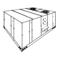
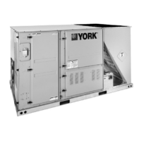
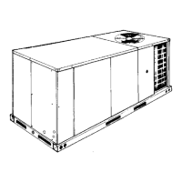
Overview of YORK Model DCG units, their assembly, and key features.

CRITICAL SAFETY GUIDELINES

Essential safety instructions regarding gas leaks, flammable vapors, and general precautions.

INSPECTION AND SUPPORT RESOURCES

Procedures for unit inspection and listing of related technical documents.

AGENCY APPROVALS

Lists the design certifications by U.L. & CGA.

Installation - Site Preparation

LIMITATIONS AND CODES

Lists national and local safety codes the unit must be installed according to.

LOCATION AND CLEARANCES

Guidelines for unit placement, ventilation, and required clearances.

RIGGING AND HANDLING

Instructions for safely moving and lifting the unit during installation.

DUCTWORK DESIGN

Guidance on designing and sizing ductwork for the unit.

Installation - Component Setup

COMPRESSORS AND FILTERS

Details on compressor mounting and filter installation.

THERMOSTAT AND WIRING

Recommendations for thermostat location, wiring, and power connections.

SERVICE ACCESS AND UTILITY ENTRY

Locations of panels for access and utilities entry points.

Installation - Gas System

COMBUSTION DISCHARGE

Location of combustion product discharge.

GAS PIPING AND CONNECTION

Guidelines for proper gas piping sizing and unit connection.

Gas and Venting Installation Details

LP GAS CONVERSION AND PIPING

Information on converting to L.P. gas and related piping.

VENT AND COMBUSTION AIR HOODS

Installation instructions for vent and combustion air hoods.

Economizer Setup Procedure

ENTHALPY SETPOINT ADJUSTMENT

Procedure for setting the enthalpy setpoint for dampers.

Unit Dimensions and Utility Entry

DIMENSIONS AND CLEARANCES

Detailed dimensions and clearance requirements for the unit.

UTILITIES ENTRY DATA

Specifies sizes and uses for utility entry points on the unit.

Unit Operation

COOLING SYSTEM OVERVIEW

Details the air-cooled condenser and compressor system.

COOLING SEQUENCE

Explains how the unit operates during cooling cycles.

HEATING SEQUENCE

Describes the operation of the gas heat section.

REFRIGERANT SAFETY CONTROLS

Details the refrigerant system safety controls and their functions.

Operational Checks and Settings

SAFETY CONTROL FUNCTIONS

Explains the limit control, centrifugal switch, redundant gas valve, and flame sensor.

HEAT ANTICIPATOR SETPOINTS

Guidance on setting heat anticipator values for proper cycle control.

PRE-START CHECKLIST

A list of essential checks to perform before initial unit startup.

Start-Up and Gas System Checks

OPERATING INSTRUCTIONS

Basic steps for operating the unit and lighting the pilot.

POST-START GAS CHECKS

Checks for gas leaks and manifold pressure after startup.

GAS PRESSURE ADJUSTMENT

How to adjust the gas pressure regulator for optimal performance.

PILOT AND BURNER ADJUSTMENT

Procedures for adjusting the pilot flame and burner assembly.

Airflow and Burner Performance

TYPICAL FLAME APPEARANCE

Visual guide to proper burner flame characteristics.

BURNER AIR SHUTTER ADJUSTMENT

How to adjust burner shutters for optimal combustion.

SUPPLY AIR CFM MEASUREMENT

Method for checking and calculating the supply air CFM.

BLOWER PULLEY ADJUSTMENT

How to adjust the blower motor pulley for desired CFM.

Performance Tuning and Input Verification

TEMPERATURE RISE ADJUSTMENT

How to adjust blower CFM to meet temperature rise specifications.

GAS INPUT RATE CHECK

Procedure for verifying the unit's gas input rate.

OWNER APPROVAL AND TRAINING

Securing owner approval and providing operational training.

Maintenance Procedures

NORMAL MAINTENANCE TASKS

Routine checks for filters, motors, outdoor coil, and burners.

CLEANING FLUE PASSAGES AND ELEMENTS

Procedures for cleaning heat exchangers and flue passages.

Troubleshooting Common Issues

TROUBLESHOOTING PRECAUTIONS

Safety warnings and general guidance for troubleshooting.

BLOWER AND IGNITION FAULTS

Diagnosing problems with blower start-up and ignition sequences.

DRAFT MOTOR AND GAS VALVE ISSUES

Troubleshooting draft motor operation and gas valve related problems.

Replacement Parts and Service Information

REPLACEMENT PARTS LIST

Lists common replacement parts by section (Compressor, Motor, Gas Heat, etc.).

OBTAINING PARTS AND SERVICE

How to order parts and contact for service.

IMPORTANT SERVICE WARNINGS

Crucial warnings regarding improper installation, adjustment, or maintenance.

Related product manuals