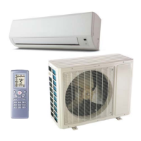
Do you have a question about the York DHMF24CMM42Q1A and is the answer not in the manual?
Details the Multi Zone Series ductless climate systems, designed for optimum performance and efficiency.
Highlights features like variable frequency rotary compressor, low ambient cooling, and defrost control.
Outlines the standard 2-year limited parts and 6-year limited compressor warranty.
Explains the structure of model numbers including type, SEER, capacity, and configuration.
Details cooling and heating capacities, EER, SEER, and HSPF for various models.
Provides specifications for indoor units, including fan motor, evaporator, and dimensions.
Lists compressor data, operating ranges, pipe diameters, and air flow for outdoor units.
Details dimensions, package dimensions, and weight for outdoor units.
Graphs showing current draw relative to compressor speed for cooling and heating modes.
Charts illustrating capacity ratio changes based on outdoor temperature in cooling and heating.
Table showing temperature conditions, model names, pressures, and compressor frequencies.
Presents noise levels for indoor units at different fan motor speeds.
Graphs showing outdoor unit noise levels as a function of compressor frequency.
Diagrams and table showing dimensions (A, B, C) and gross weight for indoor units.
Diagrams and table showing dimensions (A, B, C) and gross weight for outdoor units.
Diagram illustrating the refrigerant flow and components within the multi-zone system.
Details wiring symbols, color codes, and part names for indoor and outdoor units.
Diagram and notes for the electrical wiring of the 18K outdoor heat pump unit.
Diagram and notes for the electrical wiring of the 24K outdoor heat pump unit.
Diagram and notes for the electrical wiring of the 30K outdoor heat pump unit.
Diagram and notes for the electrical wiring of the 42K outdoor heat pump unit.
Explains cooling, heating, and dry modes, including fan operation and defrosting.
Details how the system handles conflicting modes and various protection mechanisms.
Lists sensors and the conditions that trigger fault detection for each.
Table providing resistance values for ambient temperature sensors at various temperatures.
Table showing resistance values for indoor and outdoor tube temperature sensors.
Table providing resistance values for outdoor discharge temperature sensors.
Instructions for before disassembly, removing the filter, and removing the display unit.
Steps for removing the main panel and the horizontal louver assembly.
Procedure for removing the top cover of the electric box.
Instructions for removing the front case and the earthing wire.
Steps to loosen clasps and remove the main electric box cover.
Procedure for removing the temperature sensor and the electric box.
Steps to remove the water tray and the connection pipe between units.
Instructions for removing the pipe-stopping plate and damping board.
Steps for removing the evaporator and the motor fixing plate.
Procedure for removing the cross flow blade and motor assembly.
Instructions for removing cushion rubber from the cross flow blade and base.
Steps to remove the top panel, valve cover, and front side panel.
Instructions for removing the grille and the main outer panel.
Procedure for removing the guard grille and the unit handle.
Steps to remove the right side plate and the electric box cover.
Instructions for removing the electric box and the left side plate.
Procedure for removing the axial flow blade from the unit.
Steps to remove the motor and its support assembly.
Procedure for removing the 4-way valve and the gas/liquid valves.
Instructions for removing the compressor and the isolation sheet.
Steps to remove the condenser support plate and the chassis.
List of part numbers for accessories, mounting hardware, and condensate handling.
Catalog of part numbers for insulated linesets, covers, and various fittings.
| Phase | 1 |
|---|---|
| Refrigerant | R-410A |
| Cooling Capacity | 24000 BTU/h |
| Voltage | 208-230V |
| Power Supply | 208-230V/60Hz/1Ph |
| Heating Capacity | 24000 BTU/h |


 Loading...