EasyManua.ls Logo

York DHUC 060 - User Manual

York DHUC 060
20 pages
Print Icon
To Next Page IconTo Next Page
Loading...
GENERAL
Model DUC units are single package air conditioners with gas
heat designed for outdoor installation on a rooftop or a slab.
The units are completely assembled on rigid, permanently
attached base rails. All piping, refrigerant charge, and electrical
wiring is factory-installed and tested. The units require only electric
power, gas piping and duct connections at the point of installation.
The gas-fired heaters have aluminized steel tubular heat
exchangers and spark ignition with intermittent pilot.
This appliance is not to be used for temporary heating of
buildings or structures under construction.
INSPECTION
As soon as a unit is received, it should be inspected for possible
damage during transit. If damage is evident, the extent of the
damage should be noted on the carrier’s freight bill. A separate
request for inspection by the carrier’s agent should be made in
writing.
REFERENCE
Additional information on the design, installation, operation and
service of this equipment is available in the following reference forms:
530.18-N1.2V -Economizer Accessory
530.18-N1.13V -Man. Outdoor Air Damper Accy 0-35%
530.18-N1.14V -Man. Outdoor Air Damper Accy 0-100%
530.18-N1.12V -Motorized Outdoor Air Damper Accy.y
530.18-N1.8V -Coil Guard
530.18-N2.11V -Low NOx Accessory
530.18-N8.2V -High Altitude Accy. (Natural Gas)
530.18-N8.3V -High Altitude Accy. (Propane)
530.18-N8.4V -Gas Piping Accessory
530.18-N8.12V -Propane Conversion Accessor
690.15-N25V -Low Ambient Accessory
Renewal Parts:
Refer to Parts Manual for complete listing of replacement
parts on this equipment.
All forms referenced in this instruction may be ordered from:
Publications Distribution Center
Unitary Products Group
P.O. Box 1592, York, PA 17405
APPROVALS
Design certified by CGA and UL listed as follows:
1. For use as a forced air furnace with cooling unit.
2. For outdoor installation only.
3. For installation directly on combustible flooring or, in the U.S.A.,
on wood flooring or Class A, B, or C roof covering material.
4. For use with natural gas and/or propane (LP) gas.
Not suitable for use with conventional venting systems.
Installer should pay particular attention to the words:
NOTE, CAUTION
and
WARNING
. Notes are intended to clarify or make
the installation easier. Cautions are given to prevent equipment damage. Warnings are given to alert installer that personal injury
and/or equipment damage may result if installation procedure is not handled properly.
CAUTION
THIS PRODUCT MUST BE INSTALLED IN STRICT COMPLIANCE WITH THE ENCLOSED INSTALLATION INSTRUCTIONS
AND ANY APPLICABLE LOCAL, STATE, AND NATIONAL CODES INCLUDING, BUT NOT LIMITED TO, BUILDING, ELECTRI-
CAL, AND MECHANICAL CODES
WARNING
INCORRECT INSTALLATION MAY CREATE A CONDITION WHERE THE OPERATION OF THE PRODUCT COULD CAUSE
PERSONAL INJURY, PROPERTY DAMAGE AND/OR DEATH.
WARNING
DE-ENERGIZE THE ELECTRICAL POWER AND TURN OFF THE GAS SUPPLY TO THE UNIT BEFORE ATTEMPTING TO
INSPECT, REPAIR OR PERFORM MAINTENANCE TO THE UNIT.
CAUTION
SCROLL COMPRESSORS
OPERATE IN ONLY ONE
DIRECTION.
If the compressor is
experiencing:
- low amperage draw
- similar discharge and
suction pressure
- increased noise level
It is operating in reverse.
Switch two line voltage
connections to correct.
FOR YOUR SAFETY
Do not store or use gasoline or
other flammable vapors or liquids
in the vicinity of this or any other
appliance
.
If you smell gas:
1. Open windows
2. Don’t touch electrical switches.
3. Extinguish any open flame.
4. Immediately call your gas supplier.
035-14839
MODELS DHUC 036, 048 & 060 (10 SEER)
MODEL DBUC 072 (9 EER)
(STYLE A & Belt-Drive Option)
INSTALLATION
INSTRUCTION
GAS / ELECTRIC
SINGLE PACKAGE AIR CONDITIONERS
Supersedes: 530.18-N8W (295)
530.18-N8W (1096)

Table of Contents

Question and Answer IconNeed help?

Do you have a question about the York DHUC 060 and is the answer not in the manual?

Summary

GENERAL INFORMATION

Initial Unit Inspection

Details the process for inspecting the unit upon delivery.

Safety Warnings and Approvals

Highlights safety precautions and certifications.

INSTALLATION LIMITATIONS AND GUIDELINES

ELECTRICAL AND GAS CONNECTIONS

Power and Control Wiring

Covers field wiring requirements and safety precautions.

Gas Piping Installation

Guidelines for sizing and connecting the gas supply line.

UNIT OPERATION MODES

Cooling System Operation and Safety

Explains cooling cycles and safety controls.

Heating System Operation and Safety

Details heating cycles and safety controls.

HEATING SYSTEM ADJUSTMENTS AND CHECKS

Limit Controls and Heat Anticipator Settings

Adjustments for temperature controls.

Pre-Start Checklist and Gas Pressure

Pre-operation checks and manifold pressure adjustment.

BURNER AND BLOWER PERFORMANCE ADJUSTMENT

Pilot Flame and Burner Adjustments

Procedures for pilot checkout and burner settings.

GAS INPUT VERIFICATION AND PERFORMANCE

ROUTINE MAINTENANCE PROCEDURES

TROUBLESHOOTING GUIDE

Draft Motor and Ignition System Issues

Diagnosing problems with the draft motor and ignition.

Burner Ignition and Flame Issues

Troubleshooting burner ignition and flame characteristics.

Overview

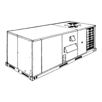
This document provides installation and operation instructions for Gas/Electric Single Package Air Conditioners, specifically models DHUC 036, 048 & 060 (10 SEER) and DBUC 072 (9 EER), available in Style A with an optional Belt-Drive. These units are designed for outdoor installation on a rooftop or a slab and come completely assembled with factory-installed and tested piping, refrigerant charge, and electrical wiring. They require only external electric power, gas piping, and duct connections at the installation site. The gas-fired heaters feature aluminized steel tubular heat exchangers and spark ignition with an intermittent pilot.

Function Description

These units provide both cooling and heating for forced air systems. For cooling, they utilize an air-cooled condenser and are factory-charged with Refrigerant-22. The scroll compressor is hermetically sealed and internally sprung, with inherent internal protection against abnormal temperature rise. For heating, gas-fired heaters with aluminized steel tubular heat exchangers provide warmth, controlled by a spark ignition with an intermittent pilot. The system is designed for outdoor installation only and is not suitable for temporary heating of buildings or structures under construction.

Important Technical Specifications

  • Unit Sizes:
    • DHUC: 036 (3 Ton), 048 (4 Ton), 060 (5 Ton)
    • DBUC: 072 (6 Ton)
  • SEER/EER: 10 SEER for DHUC models, 9 EER for DBUC 072.
  • Voltage Variations:
    • 208/230V (Min./Max. 187/253V)
    • 460V (Min./Max. 414/504V)
    • 575V (Min./Max. 518/630V)
  • Supply Air CFM, Nominal:
    • 036: 1200 CFM
    • 048: 1600 CFM
    • 060: 2000 CFM
    • 072: 2400 CFM
  • Evaporator Coil Wet Bulb Temperature: 57/72°F (Min./Max.)
  • Condenser Coil Dry Bulb Temperature: 45/120°F (Min./Max.) (A low ambient accessory is available for operation down to 0°F).
  • Gas Heating Input Capacity (Mbh): 50, 75, 100, 125.
  • Gas Heating Output Capacity (Mbh): 40, 60, 79, 99.
  • Temperature Rise at Full Input: Ranges from 15-45°F (50 Mbh) to 45/35/35-75/65/65°F (125 Mbh), depending on the model.
  • Blower Motors:
    • Direct-Drive: 1/2 HP (036), 3/4 HP (048), 1 HP (060, 072).
    • Belt-Drive (Optional): 1-1/2 HP for all models.
  • Refrigerant Charge (R-22): 5/8 lbs./oz. (036), 6/8 lbs./oz. (048, 060), 10/0 lbs./oz. (072).
  • Electrical Data (Direct-Drive):
    • 036 (208/230-1-60): RLA 18.0, LRA 105.0, Min. Circuit Ampacity 28.2, Max. Fuse/HACR Breaker 45 Amps.
    • 072 (460-3-60): RLA 10.2, LRA 73.0, Min. Circuit Ampacity 17.2, Max. Fuse/HACR Breaker 25 Amps.
  • Electrical Data (Belt-Drive):
    • 036 (208/230-1-60): RLA 18.0, LRA 105.0, Min. Circuit Ampacity 29.1, Max. Fuse/HACR Breaker 45 Amps.
    • 072 (460-3-60): RLA 10.2, LRA 73.0, Min. Circuit Ampacity 17.3, Max. Fuse/HACR Breaker 25 Amps.
  • Safety Controls (Cooling): Suction Line Freezestat, High Pressure Cutout Switch, Low Pressure Switch.
  • Safety Controls (Heating): Limit Control (LS), Centrifugal Switch (CS-36), Redundant Gas Valve, Flame Sensor Rod, Rollout Switch, Auxiliary Limit Switch.

Usage Features

  • Outdoor Installation: Designed for rooftop or slab mounting.
  • Ductwork: Supply and return air duct connections should be made with flexible joints to minimize noise. Ductwork should be insulated and waterproofed.
  • Filters: 1" filters are supplied, 2" replacement filters can be used. Filters must be kept clean to maintain unit capacity and prevent frosted coils or safety shutdown.
  • Condensate Drain: A 3/4" PVC female connection is provided for the condensate drain line, which must be trapped for proper drainage.
  • Thermostat Control: A 24-volt room thermostat is used for operation. Two-stage cooling is supported with an economizer, where the economizer provides first-stage cooling and the scroll compressor provides second-stage cooling. Continuous blower operation is possible.
  • Gas Connection: Gas supply can be routed through knockouts on the front or through the unit's base. A drip leg and ground joint union must be installed. Special pipe compound is required for LP/propane gas due to its solvent properties.
  • Low NOx Application: Accessory model 1LN0404 is available for natural gas heat installations requiring low Nitrous Oxide emissions.
  • Blower Speed Selection: Direct-drive units have three blower motor speeds (HIGH, MED, LOW) selectable by wiring. Belt-drive units have an adjustable motor pulley for CFM adjustment.
  • Start-Up Procedure: Includes checks for gas type, vent and combustion air hood installation, and a detailed sequence for lighting the pilot and main burners.
  • Manifold Gas Pressure Adjustment: Small adjustments to high-fire gas flow can be made via the pressure regulator adjusting screw on the automatic gas valve.
  • Pilot Checkout: The pilot flame should envelop 3/8 inches of the flame sensor. Adjustment is made via a screw on the gas valve.
  • Burner Air Shutter Adjustment: Shutters can be adjusted to obtain a distinct, sharp, blue flame.
  • Supply Air Blower and Temperature Rise Adjustments: Blower speed is adjusted based on required CFM, unit accessories, and static resistances. For belt-drive units, the variable pitch pulley is adjusted. Temperature rise must be within the range specified on the rating plate.
  • Checking Gas Input: Involves measuring the time for one revolution of the smallest dial on the gas meter and using a provided table to determine cubic feet per hour. Input should be within 5% of the furnace rating.

Maintenance Features

  • Periodic Maintenance: Normally involves changing or cleaning filters and, under certain conditions, cleaning the main burners.
  • Filter Inspection: Inspect monthly, replace disposable filters or clean permanent ones.
  • Motor Lubrication: Indoor fan and outdoor fan motors are permanently lubricated and require no maintenance. The ventor motor is factory lubricated for an estimated 10-year life.
  • Outdoor Coil Cleaning: Clean as necessary with a brush, vacuum, or water (with power off).
  • Burner & Pilot Inspection: Annually, visually check pilot and main burner flame. Adjust primary air shutters if needed. Clean burners with hot water if necessary.
  • Combustion Air Discharge Inspection: Periodically inspect for soot and dirt buildup.
  • Cleaning Flue Passages and Heating Elements: If sooted, elements can be cleaned by removing the burner assembly, roof over the gas heat section, flue collector box, and flue diverter baffle, then brushing out the heat exchangers and flue components.
  • Troubleshooting Guide: Provides detailed steps for diagnosing common issues such as draft motor operation, furnace ignition, sparker function, pilot ignition, main burner ignition, and erratic flame characteristics. Includes checks for electrical connections, voltage, relays, switches, and gas supply.
  • Safety Precautions: Emphasizes de-energizing electrical power and turning off gas supply before inspection, repair, or maintenance. Warnings are provided for working with live circuits during troubleshooting.
  • Owner's Approval: After proper system function is confirmed, the installer should secure the owner's approval, demonstrate disconnect switch locations and thermostat operation.

York DHUC 060 Specifications

General IconGeneral
BrandYork
ModelDHUC 060
CategoryAir Conditioner
LanguageEnglish

Related product manuals