GENERAL
This instruction covers the installation of the following outdoor
units:
The outdoor units are designed to be connected to a matching
evaporator with sweat connect lines and are factory charged
with refrigerant for a matching evaporator plus 15 feet of field
supplied lines.
Matching evaporators contain an orifice liquid feed sized for the
most common usage. The orifice size and/or refrigerant charge
may need to be changed for some indoor-outdoor unit combi-
nations, elevation differences or total line lengths.
INSPECTION
As soon as a unit is received, it should be inspected for possible
damage during transit. If damage is evident, the extent of the
damage should be noted on the carrier’s delivery receipt. A
separate request for inspection by the carrier’s agent should
be made in writing. See Local Distributor for more information.
REFERENCE
Use this instruction in conjunction with the instruction for the
appropriate indoor unit, air moving system and accessories.
Installer should pay particular attention to the words:NOTE,
CAUTION and WARNING.
NOTES are intended to clarify or make the installation easier.
CAUTIONS identifies procedure which, if not followed carefully,
could result in personal injury, property damage or product
damage.
WARNINGS are given to alert the installer that personal injury
and/or equipment damage may result if installation procedures
are not handled properly.
NOMENCLATURE
LIMITATIONS
The unit should be installed in accordance with all national and
local safety codes.
Limitations for the indoor unit, coil and appropriate accessories
must also be observed. For piping limitations and additional
requirements refer to piping guide 690.01-AD1Y.
The outdoor unit must not be installed with any ductwork in the
air stream. The outdoor fan is the propeller type and is not
designed to operate against any additional external static pres-
sure.
The unit should not be operated at temperatures below 45°F.
LOCATION
Before starting the installation, select and check the suitability
of the location for both the indoor and outdoor unit. Observe all
limitations and clearance requirements, see Figure 1.
The outdoor unit must have sufficient clearance for air entrance
to the condenser coil, for air discharge and for service access.
NOTE: For multiple unit installations, units must be spaced a
minimum of 18 inches apart (coil face to coil face).
If the unit is to be installed on a hot sun exposed roof or a
black-topped ground area, the unit should be raised sufficiently
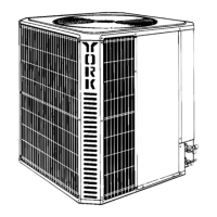
NDEN
IN
UNIT
SPLIT-SYSTEM COOLING
2 TO 5 TONS
Supersedes: 550.36-N2Y (894)
035- 13122
MODELS H2DH024 thru H2DH060
H2DH024S06
H2DH030S06
H2DH036S06
H2DH042S06
H2DH048S06
H2DH060S06
Voltage Code
Refrigerant Line Connections
Nominal Cooling Capacity
H
061
DH
Product Category
Product Identifier
H = Condensing Unit
1,2 = Design Level
DH = 12.00 SEER Condensing Unit
024=24,000 BTUH
030=30,000 BTUH
036=36,000 BTUH
042=42,000 BTUH
048=48,000 BTUH
060=60,000 BTUH
S = Sweat-Connect
06 = 208/230-1-60
®
INSTALLATION INSTRUCTION