841890-UIM-B-0612
2
SECTION II: GENERAL INFORMATION
This instruction covers the installation of the following coils with 80+ or
90+ AFUE furnaces or MA/MX/MV air moving systems.
The coils have sweat connect fittings. All coils are shipped with a low
psi nitrogen holding charge.
INSPECTION
As soon as a coil is received, it should be inspected for possible dam-
age during transit. If damage is evident, the extent of the damage
should be noted on the carrier’s delivery receipt. A separate request for
inspection by the carrier’s agent should be made in writing. See Local
Distributor for more information. Check drain pan for cracks or break-
age.
CLEARANCES
DURING INSTALLATION
Clearance must be provided for:
1. Refrigerant piping and connections
2. Maintenance and servicing access - including cleaning the coil
3. Condensate drain line
4. Filter removal / change
5. Removal of coil assembly
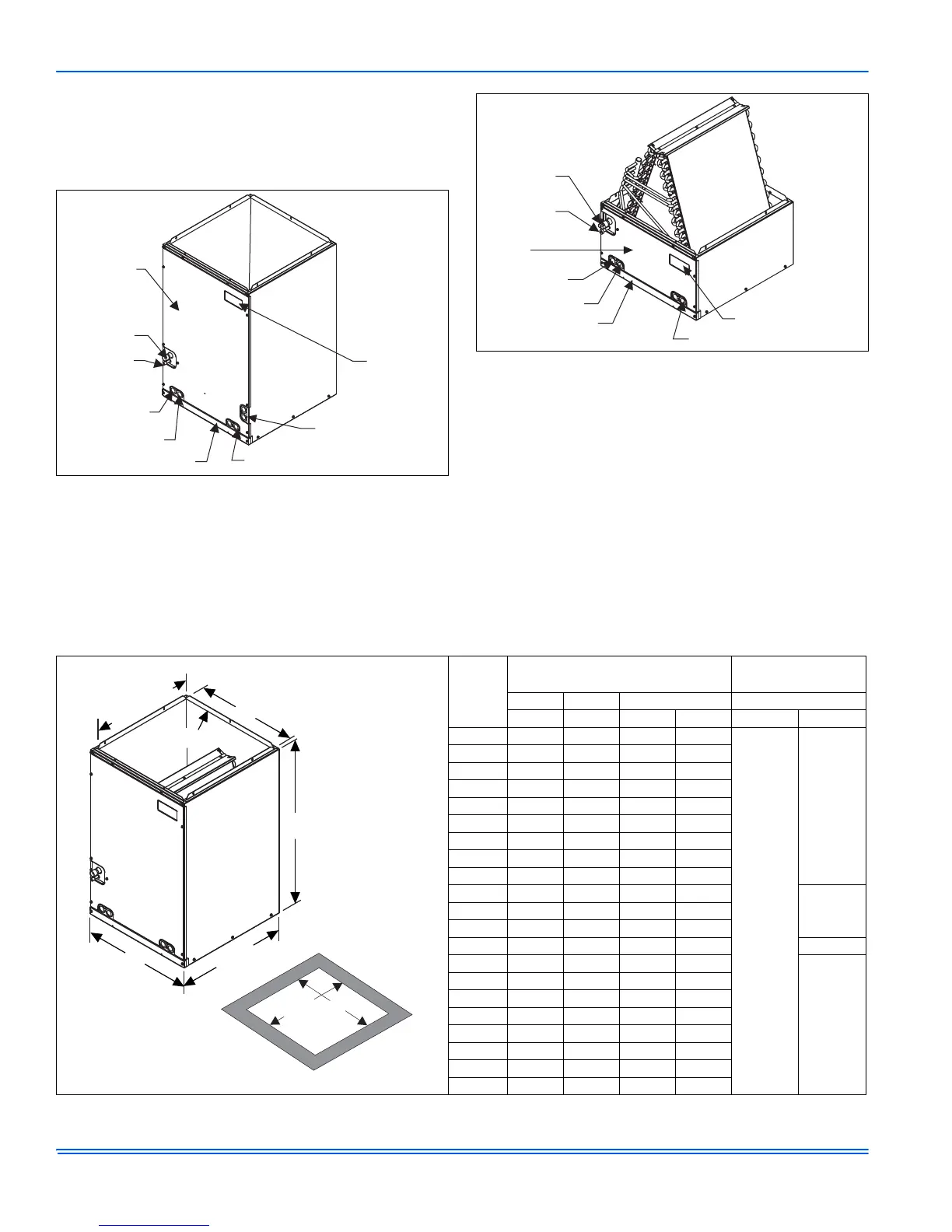
FIGURE 1: Component Location - Coil MC & FC
Coil Access
Panel
Suction Line
Connection
Liquid Line
Connection
Alternate Drain Location
Label
Location
Drain Location
Horizontal Application
(on MC Coils Only)
Primary Drain
Secondary Drain
Bottom Door Panel
FIGURE 2: Component Location - Coil PC
Label Location
Coil Access
Panel
Primary Drain
Secondary Drain
Bottom Door Panel
Alternate Drain Locations
Suction Line
Connection
Liquid Line
Connection
TABLE 1: Dimensions
- MC Coils
Models
Dimensions
1
1. All dimensions are in inches.
Refrigerant
Connections
2
2. Refrigerant line sizes may require larger lines for extended line lengths. See York bulletin #690.01-AD1V for details.
Height Width Opening Widths Line Size
ABCDLiquidVapor
MC18A 22 14 1/2 13 3/8 13 1/2
3/8
3/4
MC18B 22 17 1/2 16 3/8 16 1/2
MC24A 26 1/2 14 1/2 13 3/8 13 1/2
MC24B 26 1/2 17 1/2 16 3/8 16 1/2
MC30A 26 1/2 14 1/2 13 3/8 13 1/2
MC30B 26 1/2 17 1/2 16 3/8 16 1/2
MC32A 22 14 1/2 13 3/8 13 1/2
MC35B 22 17 1/2 16 3/8 16 1/2
MC35C 22 21 19 7/8 20
MC36A 26 1/2 14 1/2 13 3/8 13 1/2
7/8MC36B 26 1/2 17 1/2 16 3/8 16 1/2
MC36C 26 1/2 21 19 7/8 20
MC37A 26 1/2 14 1/2 13 3/8 13 1/2 3/4
MC42B 32 17 1/2 16 3/8 16 1/2
7/8
MC42C 32 21 19 7/8 20
MC43B 26 1/2 17 1/2 16 3/8 16 1/2
MC43C 26 1/2 21 19 7/8 20
MC48C 32 21 19 7/8 20
MC48D 32 24 1/2 23 3/8 23 1/2
MC60D 32 24 1/2 23 3/8 23 1/2
MC62D 36 24 1/2 23 3/8 23 1/2
20 3/8”
(Opening)
B
C
3/4” Flange
A
21 1/2”
BOTTOM
OPENING
DIMENSIONS
D
20 1/4”
 Loading...