Do you have a question about the York MCC-MCH and is the answer not in the manual?
Lists items shipped with the indoor unit, including mounting bracket, remote, user guide.
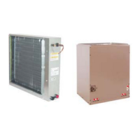
States outdoor units are shipped with R22 refrigerant for a 5-meter piping length.
Specifies minimum clearances required around indoor and outdoor units for optimal airflow and maintenance access.
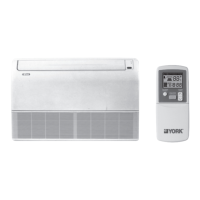
Details how to install indoor units vertically at floor level, horizontally beneath a ceiling, or vertically on a wall.
Describes how to use the emergency switch for manual operation when the remote control is unavailable or faulty.
Details how to adjust the desired room temperature using the TEMP buttons, with a recommended operating range.
Explains how to adjust fan speed and control louver movement using dedicated buttons on the remote control.
Provides instructions for cleaning air filters and resetting the filter alarm indicated by flashing lights.
Details how to set the clock and program start/stop timers for the unit's operation.
Describes the sleep mode program designed for comfortable room environments during sleep hours, adjusting temperature gradually.
Explains how the diagnostic system reports operational status and failures through indicator light patterns.