Do you have a question about the York MILLENNIUM YK and is the answer not in the manual?
Explanation of the alphanumeric code used to identify chiller models and their components.
Describes how the YORK Model YK Millennium Chiller operates and its primary components.
Explains how chiller capacity is modulated using prerotation vanes to maintain chilled liquid temperature.
Introduces the MicroComputer Control Center, its display, and keypad functions.
Details the control center's setpoints, display parameters, and EMS interface capabilities.
Describes the front panel layout, key groups, display, and how to display system parameters.
Explains how to use display keys to view specific system parameters like temperatures and pressures.
Defines and explains setpoints such as Chilled Liquid Temp, Current Limit, and Pull Down Demand.
Details setpoints like Clock, Daily Schedule, Holiday, Remote Reset Temp Range, and Data Logger.
Describes the procedure to view programmed setpoint values on the control center display.
Explains how to display undervoltage setpoints and access data logger functions.
Step-by-step guide on how to access and program system setpoints using the control center keypad.
Detailed instructions for programming the Leaving Chilled Water Temperature and Current Limit setpoints.
Guides on programming Pull Down Demand Limit and Clock (Time of Day) setpoints.
Instructions for programming daily start and stop times, including holiday schedules.
Details on programming holiday designations and remote reset temperature range setpoints.
Describes how to manually control the prerotation vanes using the OPEN, HOLD, CLOSE, and AUTO keys.
Explains manual control of refrigerant level valve and VSD oil pump speed.
Details how to use the DISPLAY DATA key to view various system parameters during troubleshooting.
Provides steps to change the control center's operating mode (LOCAL, REMOTE, SERVICE, PROGRAM).
Explains the operation of the compressor start, run, and stop/reset switch.
Lists and describes various "SYSTEM RUN" messages indicating operational status and limits.
Lists and describes system shutdown messages, including causes and restart procedures.
Details shutdown messages related to motor controllers, power faults, high temperatures, and pressure transducer errors.
Covers shutdowns due to program errors, starter malfunctions, and phase current unbalance.
Describes shutdowns related to proximity sensors, drain temperature, and safety probe errors.
Covers shutdowns from thermocouple errors, DC undervoltage, and auxiliary safety inputs.
Explains the function, control, and operation of the oil heaters.
Details the chiller start-up sequence and the basic operation of the chiller after startup.
Illustrates the start-up and shutdown sequence and discusses condenser water temperature control.
Describes the importance and method of keeping a daily record of system operating conditions.
Lists daily checks for the control center, oil pressure, temperatures, and pressures.
Explains normal and safety shutdowns, differentiating between them and their reset requirements.
Outlines procedures for shutting down the chiller for extended periods and restarting it.
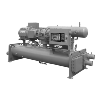
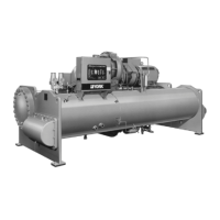
Provides visual identification of major chiller components like the compressor, cooler, and motor.
Details the compressor type, design, capacity control, and the lubrication system components.
Describes the construction of heat exchangers (evaporator/condenser) and refrigerant flow control.
Explains optional features like service valves, hot gas bypass, Solid State Starter, and VSD.
Covers the oil return system and the procedure for changing the dehydrator.
Details the compressor oil charge requirements and the step-by-step procedure for adding oil.
Lists causes of normal and safety system shutdowns and the required restart methods.
Analyzes common operating symptoms like high discharge pressure, low suction, and high cooler pressure.
Addresses issues like no oil pressure, fluctuating oil pressure, noisy pumps, and reduced pump capacity.
Details procedures for checking system for leaks and performing evacuation and dehydration.
Explains vacuum testing procedures and provides a table of system pressures.
Describes the process of dehydrating the system using vacuum and saturation curves.
Guides on refrigerant charging procedures and checking the charge level during shutdown.
Covers procedures for handling refrigerant and testing motor windings with a megohmmeter.
Discusses general maintenance for condensers/coolers and types of tube fouling.
Details methods for cleaning condenser and cooler tubes, including brush and acid cleaning.
Details requirements for oil filter changes, oil changes, and motor checks.
Covers checking motor mounting screws and meggering motor windings annually.
Recommends cleaning condenser tubes annually and cooler tubes as needed.
Specifies changing the dehydrator in the oil return system semi-annually.
Provides factors for converting English measurements to SI Metric values and temperature ranges.





 Loading...