EasyManua.ls Logo

York MOC-MOH 07-65 User Manual

York MOC-MOH 07-65
12 pages
To Next Page IconTo Next Page
Page #1 background imageLoading...
Page #1 background image
OUTDOOR UNITS
SAFETY
CAUTION
ELECTRICAL CONNECTIONS
GENERAL PRECAUTIONS
CRANKCASE HEATER
Before undertaking any work on the unit, make sure that the power supply has been disconnected.
INSTALLATION & OWNERS
MANUAL GUIDE
MINISPLIT CONDENSING UNIT
Models
MOC-MOH 07-65
For units fitted with crankcase heater, the heater MUST be on
for a minimum of 6 hours before starting compressor. Failure to
observe this precaution may result
in damage to the compressor or reversing valve.
All electrical wiring and connections must comply with local
standards. Power supply cord and interconnection cord used
must not be lighter than Polychloroprene sheated cord
(245 IEC 57 or H05RN-F).
Disconnecting device must have a contact separation of
at least 3 mm.
Check that the power supply available agrees with nameplate
voltage.
Use adequate line protection.
The unit must be grounded.
Installation and maintenance of this air conditioning system should only be carried out by trained and qualified personnel.
Regular maintenance operations such as cleaning the coils and air filters must be performed to keep the units in proper operating
condition.
EN/FR 035T83112-001
The units are shipped complete with a charge of R22 / R407C refrigerant sufficient for a piping length of 7.5 meters.
Four vibration absorbing mounts are delivered with each unit as well as a drainage elbow connector for condensate
drain connection (on heat pump models only).
From size 25 upwards, outdoor units are fitted with transport handles to facilitate handling and placement.
Every compressor is delivered with a sound-proofing wrap to reduce noise levels to a strict minimum.
The unit support plate is shaped in such a way that water produced during defrost operations on heat pump units is
collected at a single point where it can easily drained off. No accessory drain pan is required.
Question and Answer IconNeed help?

Do you have a question about the York MOC-MOH 07-65 and is the answer not in the manual?

York MOC-MOH 07-65 Specifications

General IconGeneral
BrandYork
ModelMOC-MOH 07-65
CategoryAir Conditioner
LanguageEnglish

Summary

Unit Safety and Precautions

Safety Caution

Safety warning about disconnecting power before working on the unit.

Electrical Connection Guidelines

Guidelines for electrical wiring and connections, including power supply cord requirements.

General Electrical Precautions

Precautions for power supply voltage, line protection, and unit grounding.

Crankcase Heater Operation

Instructions for using the crankcase heater before compressor start to prevent damage.

Outdoor Unit Features

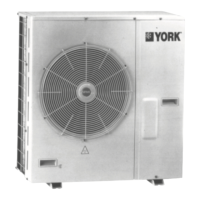
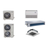
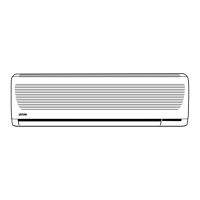
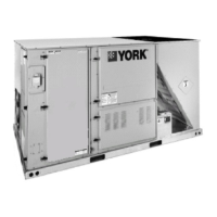
Details about the shipping, components, and features of outdoor units.

Technical Specifications Overview

R22 Condensing Units - 50 Hz

Technical specifications for MOC-MOH R22 condensing units operating at 50 Hz.

R22 Condensing Units - 60 Hz

Technical specifications for MOC-MOH R22 condensing units operating at 60 Hz.

R407C Condensing Units

Technical specifications for MOC-MOH R407C condensing units.

Unit Dimensions and Clearances

Overall Unit Dimensions

Diagrams illustrating the overall dimensions of various MOC-MOH models.

Outdoor Unit Installation Clearances

Required minimum clearances around outdoor units for proper air circulation and maintenance.

Clearance Note for Ice Build-up

Note regarding adjusting clearance C to prevent ice build-up during winter operation.

Installation Procedures and Guidelines

Unit Installation Details

Details concerning unit mounting and refrigerant piping connections.

General Installation Rules

Essential rules for unit installation to ensure proper operation and safety.

Condensate Drainage Connection

Information and guidance on connecting condensate water drainage.

Unit Wiring Connection

Information and guidance on connecting unit wiring.

Refrigerant Circuit Connections

Maximum Piping Lengths

Maximum allowable piping lengths for different model series based on elevation.

Refrigerant Charge Adjustment

Table showing additional refrigerant charge needed per meter of piping over 7.5 m.

Flare Refrigerant Piping Installation

Procedures for connecting refrigerant lines using flare connections, including evacuation and leak testing.

Pipe Work Correction Factors

MO35 Rotary Compressor Factors

Correction factors for MO35 rotary compressors based on pipe length and height difference.

MO45-65 Scroll Compressor Factors

Correction factors for MO45-65 scroll compressors based on pipe length and height difference.

Pipe Length Calculation Remarks

Remarks regarding height difference impact and equivalent pipe length calculation.

Electrical Connections and Operation

Wiring Diagrams

Wiring diagrams for cooling only and heat pump models.

Wire Size Specifications

Table detailing recommended wire sizes for MOC-MOH models.

Start-Up Procedures

Checklist and essential steps before starting the air conditioner.

Defrost Cycle Management

Explanation of the defrost cycle management and adjustable settings.

Fan Speed Controller

Slide Potentiometer Operation

Diagram and description of the slide potentiometer for fan speed control.

Cooling Circuit Pressure Tap Location

Diagram illustrating the pressure tap location on the cooling circuit.

Phase Rotation and Compressor Sounds

Scroll Compressor Phase Sequencing

Specific notes regarding phase sequencing for scroll compressors and its implications.

Compressor Operation Cautions

Cautions related to phase rotation and proper compressor operation.

Compressor Sound Characteristics

Description of normal sounds from compressors during start-up, shutdown, and flooding.

Troubleshooting Guide

Compressor and Fan Operation Problems

Troubleshooting for compressor/fan not operating, running continuously, or shutting down.

Performance and Cycling Issues

Troubleshooting for insufficient heating/cooling and unit short-cycling.

Refrigerant and Airflow Problems

Troubleshooting for low refrigerant charge or insufficient airflow.

Pressure Related Issues

Troubleshooting for excessive/insufficient discharge or suction pressure.

Technical Appendix and Operating Limits

Circuit Diagrams

Diagrams illustrating cooling and heat pump circuits for various models.

Unit Capacity Correction Factors

Factors to correct unit capacity based on temperature, piping, and fan speed.

Operating Temperature Limits

Specifies the operating temperature range for cooling and heating modes.

Start-Up Checklist and Disposal

Contractor and Equipment Details

Fields for contractor information and unit reference numbers.

Pre-Operation Checklist

Checklist of essential items to confirm before operating the unit.

Decommissioning, Dismantling & Disposal

Guidelines for decommissioning, dismantling, and disposing of the unit safely.

Related product manuals