5285473-UIM-E-1217
20 Johnson Controls Unitary Products
5. Once the correct BTU (kW) input has been established, turn the
gas valve to OFF, and turn the electrical supply switch to OFF. Then
remove the flexible tubing from the gas valve pressure port, and
tighten the pressure port plug using the 3/32” (2.4 mm) hex head
wrench.
6. Turn the electrical and gas supplies back on. With the burners in
operation, check for gas leakage around the gas valve pressure
port. Use an approved non-corrosive gas leak detection fluid or
other non-flammable leak detection methods to accomplish the leak
check.
ADJUSTMENT OF TEMPERATURE RISE
After about 5 minutes of operation, determine the furnace temperature
rise. Take readings of both the return air and the heated air in the ducts,
about six feet (1.83 m) from the furnace where they will not be affected
by radiant heat. Increase the blower speed to decrease the temperature
rise; decrease the blower speed to increase the rise.
CHECKING GAS HEAT INPUT
Natural Gas
1. Turn off all other gas appliances connected to the gas meter.
2. With the unit turned on, measure the time needed for one revolution
of the hand on the smallest dial on the meter (a typical gas meter
usually has a 1/2 or a 1 cubic foot test dial).
3. Using the number of seconds for each revolution and the size of the
test dial increment, find the cubic feet of gas consumed per hour
from Table 17.
If the actual input is not within 5% of the unit input rating with allowance
being made for the permissible range of the regulator setting, replace
the orifice spuds with spuds of the proper size.
Table 17: Gas Rate Cubic Feet Per Hour
1
1. EXAMPLE: By actual measurement, it takes 38 seconds for the hand on
the 1-cubic foot dial to make a revolution with just a 100,000 BTUH furnace
running. Using this information, locate 38 seconds in the first column of
Table 17. Read across to the column headed “1 Cubic Foot,” and see that
95 cubic feet of gas per hour are consumed by the furnace at that rate. Mul-
tiply 95 x 1050 (the BTU rating of the gas obtained from the local gas com-
pany). The result is 99,750 BTUH, which is close to the 100,000 BTUH
rating of the unit.
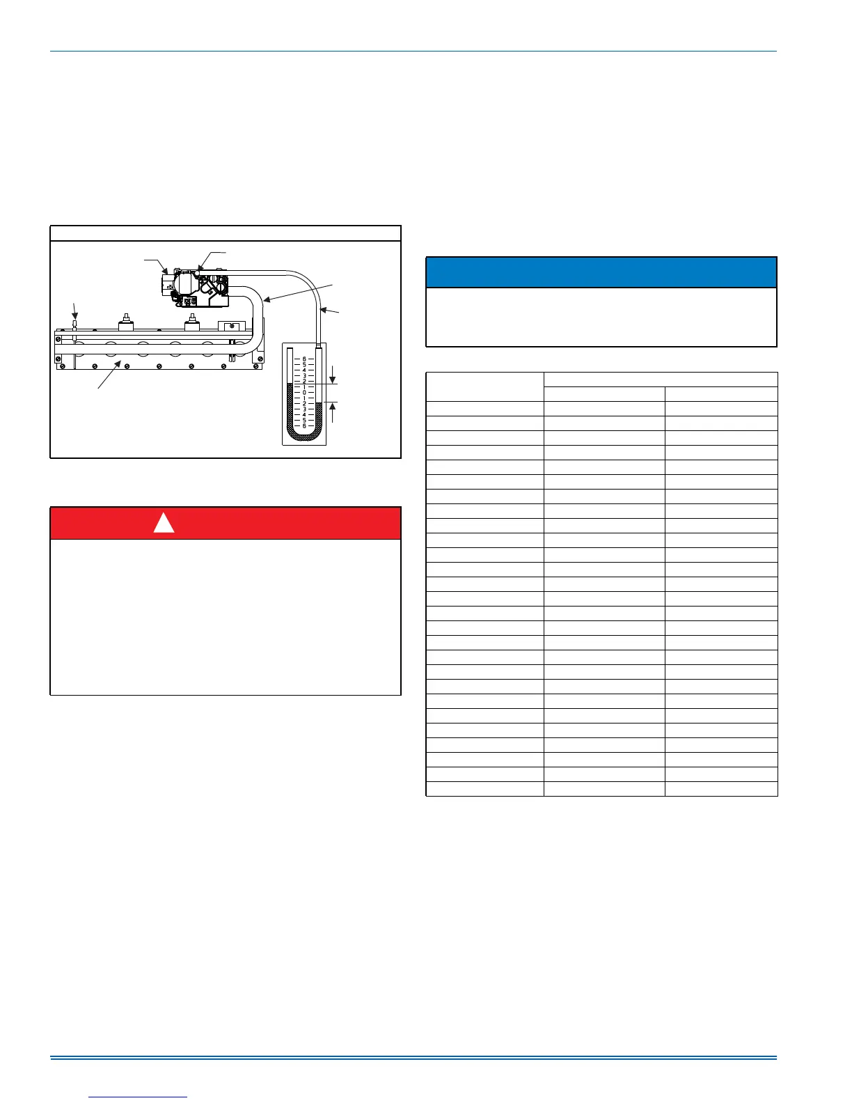
MANIFOLD PRESSURE “U” TUBE CONNECTION
FIGURE 11: Reading Gas Pressure
DANGER
The temperature rise, or temperature difference between the return
air and the supply (heated) air from the furnace, must be within the
range shown on the furnace rating plate and within the application
limitations shown in Table 7 “RATINGS & PHYSICAL / ELECTRICAL
DATA”.
The supply air temperature cannot exceed the “Maximum Supply
Air Temperature” specified in these instructions and on the furnace
rating plate. Under NO circumstances can the furnace be allowed to
operate above the Maximum Supply Air Temperature. Operating the
furnace above the Maximum Supply Air Temperature will cause pre-
mature heat exchanger failure, high levels of Carbon Monoxide, a fire
hazard, personal injury, property damage, and/or death.
%851(5
$66(0%/<
878%(
0$120(7(5
,1
:$7(5
&2/801
*$6
35(6685(
6+2:1
´78%,1*
0$1,)2/'
3,3(
*$6
9$/9(
287/(735(6685(7$3
)/$0(
6(1625
$
!
NOTICE
To find the BTU input, multiply the number of cubic feet of gas con-
sumed per hour by the BTU content of the gas in your particular
locality. (Contact your gas company for this information since it varies
widely from city to city.)
Seconds for
One Rev.
Size of Test Dial
1/2 cu. ft. 1 cu. ft.
10 180 360
12 150 300
14 129 257
16 113 225
18 100 200
20 90 180
22 82 164
24 75 150
26 69 138
28 64 129
30 60 120
32 56 113
34 53 106
36 50 100
38 47 95
40 45 90
42 43 86
44 41 82
46 39 78
48 37 75
50 36 72
52 35 69
54 34 67
56 32 64
58 31 62
60 30 60