5285477-UIM-A-1016
Johnson Controls Unitary Products 5
NOTE: For units applied with a roof curb, the minimum clearance may be reduced from 1 inch to 1/2 inch? between combustible roof curb material and this supply
air duct.
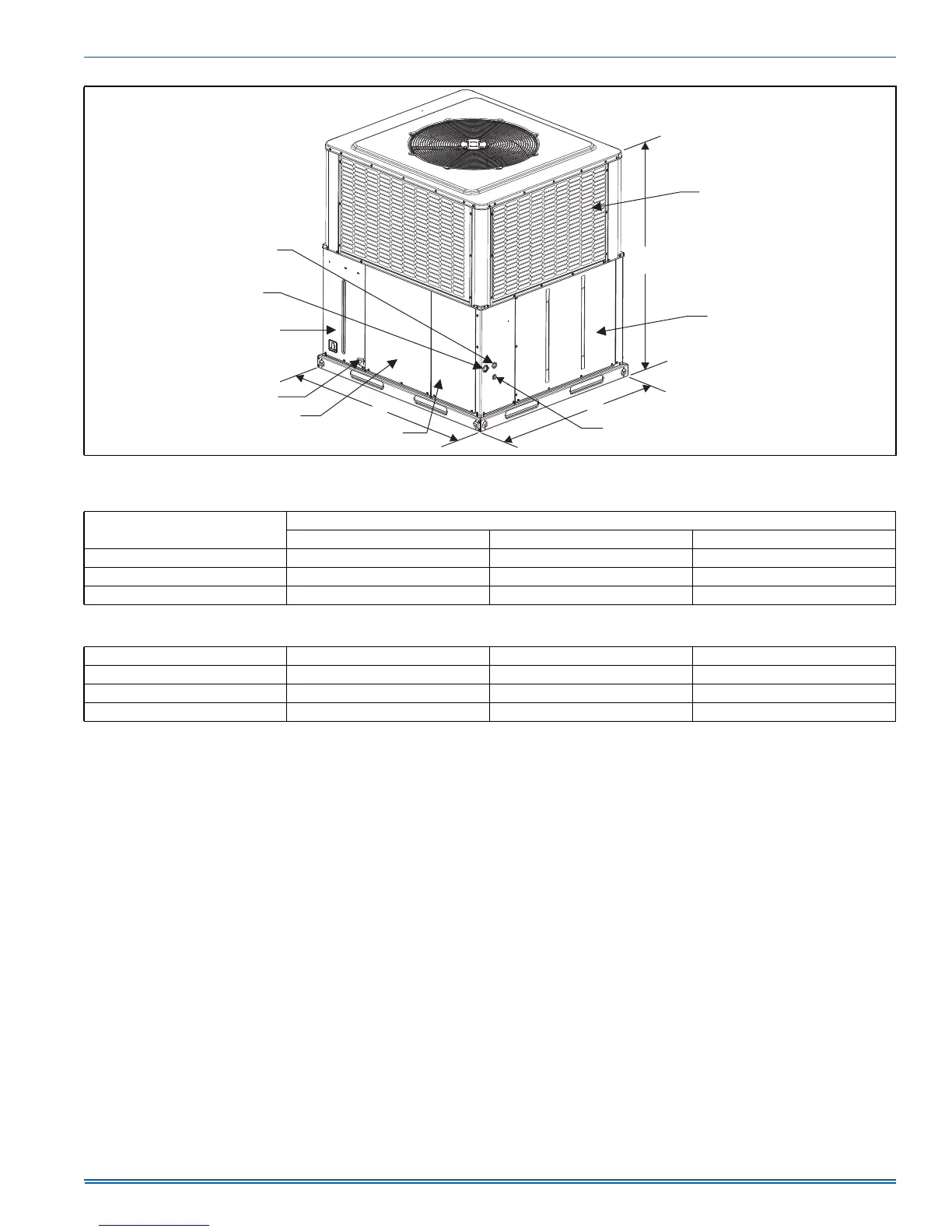
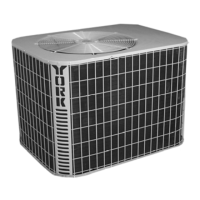
FIGURE 3: Unit Dimensions
Table 3: Unit Dimensions
Model
Dimensions (inches)
ABC
B36 51-1/4 45-3/4 49
B48 51-1/4 45-3/4 53
B60 51-1/4 45-3/4 55
Table 4: Unit Clearances
Direction Distance (inches) Direction Distance (inches)
Top
1
1. Minimum Clearance of 1inch all sides of supply air duct for the first 3 foot of duct for 20 & 25 kW., zero inches there after. For all other heaters, zero inch clearance
all sides for entire length of duct.
36 Right Side 36
Side Opposite Ducts 36 Left Side 24
Duct Panel 0 Bottom
2
3
2. Units must be installed outdoors. Over hanging structure or shrubs should not obscure outdoor air discharge outlet.
3. Units may be installed on combustible floors made from wood or class A, B or C roof covering materials.
1
HIGH VOLTAGE
CONNECTION 7/8”
HIGH VOLTAGE
CONNECTION 1-3/32”
COMPRESSOR
ACCESS PANEL
CONDENSATE
DRAIN
BLOWER
ACCESS
PANEL
CONTROL / HEAT
ACCESS PANEL
LOW VOLTAGE CONNECTION
HEAT SECTION
ACCESS PANEL
B
A
C
A0379-001
COIL GUARD