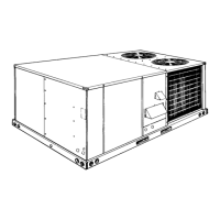
COOLING SYSTEM
The cooling section is a complete factory package utilizing an
air-cooled condenser. The system is factory-charged with
Refrigerant-22. The compressor is hermetically sealed and
internally sprung.
The compressors have inherent (internal) protection. If there is
an abnormal temperature rise in the compressor, the protector
opens to shut down the compressor.
PRELIMINARY OPERATION COOLING
After the installation has been completed, the crankcase heater
of the compressor must be energized for at least four hours
before starting the unit. After this initial warm-up, the
compressor should be given three false starts (energized just
long enough to make a few revolutions) with a five minute delay
between each start before being put into full time service.
NOTE: Prior to each cooling season, the crankcase heater
must be energized at least 10 hours before the system
is put into operation.
COOLING SEQUENCE OF OPERATION
Single-Stage Cooling:
When the thermostat calls for “cooling”, “R” is closed to “G” and
“Y1" (wiring schematic) which completes the low voltage
control circuit, immediately energizing the compressors,
condenser fan motor and blower motor simultaneously.
EXTERNAL STATIC PRESSURE DROP
DESCRIPTION
RESISTANCE, PA
M
3
/S
0.47 0.57 0.66 0.75 0.85 0.94 1.03 1.13 1.23 1.32 1.42
Economizer/Motorized Damper
1, 3
17.4 20.0 22.3 27.3 32.2 37.2 42.2 49.6 57.0 64.5 74.4
Electric Heaters
1
5 - 15 KW 10.0 12.4 15.0 17.4 20.0 24.8 29.8 34.7 39.7 47.1 54.6
20 - 30 KW 15.0 17.4 20.0 22.3 27.3 32.2 37.2 42.2 49.6 57.0 64.5
Bottom Duct Connections
1
15.0 17.4 20.0 22.3 24.8 27.3 29.8 34.7 39.7 47.1 54.6
Cooling Only
2
20.0 24.8 29.8 34.7 39.7 44.6 49.6 57.0 64.5 71.9 79.4
DESCRIPTION
RESISTANCE, IWG
CFM
1000 1200 1400 1600 1800 2000 2200 2400 2600 2800 3000
Economizer/Motorized Damper
1, 3
0.07 0.08 0.09 0.11 0.13 0.15 0.17 0.20 0.23 0.26 0.30
Electric Heaters
1
5 - 15 KW 0.04 0.05 0.06 0.07 0.08 0.10 0.12 0.14 0.16 0.19 0.22
20 - 30 KW 0.06 0.07 0.08 0.09 0.11 0.13 0.15 0.17 0.20 0.23 0.26
Bottom Duct Connections
1
0.06 0.07 0.08 0.09 0.10 0.11 0.12 0.14 0.16 0.19 0.22
Cooling Only
2
0.08 0.10 0.12 0.14 0.16 0.18 0.20 0.23 0.26 0.29 0.32
1
Deduct these resistance values from the available external static pressure shown in the Blower Performance Table.
2
Add these resistance values to the available static resistance in the Blower Performance Table.
3
The pressure thru the economizer is greater for 100% outdoor air than for 100% return air. If the resistance of the return air duct system is less than 62 Pa (0.25 IWG), the unit will deliver less
airflow during full economizer operation.
TABLE 5 - STATIC RESISTANCES
MODEL
BLOWER
RANGE
(RPM)
MOTOR*
ADJUSTABLE
MOTOR PULLEY
FIXED
BLOWER PULLEY
BELT
HP RPM FRAME
SIZE
SERVICE
FACTOR
PITCH
DIA.
BORE PITCH
DIA.
BORE PITCH LENGTH DESIG-
NATION
mm in. mm in. mm in. mm in. mm in.
DCE 060 850 - 1180 1
1
⁄
2
1450 56 1.15 69 - 97 2.8 - 3.8 22
7
⁄
8
127 5.0 25 1 947 37.3 A36
DCE 076 900 - 1200 1
1
⁄
2
1450 56 1.15 86 - 112 3.4 - 4.4 22
7
⁄
8
132 5.2 25 1 973 38.3 A37
*
All motors have solid bases and are inherently protected. These motors can be selected to operate into their service factor because they are located in the moving air, upstream of any
heating device.
TABLE 6 - MOTOR AND DRIVE DATA - Belt-Drive Blower
MODEL
DCE
POWER
SUPPLY
VOLTAGE
LIMITATIONS
1
COMPRESSOR COND.
FAN
MOTOR
FLA
SUPPLY
AIR
BLOWER
MOTOR
FLA
TOTAL
UNIT
AMPACITY
AMPS
MAX.
FUSE
SIZE
AMPS
2
MAX.
HACR
BREAKER
SIZE
AMPS
MIN.
WIRE
SIZE,
AWG
3
MIN. MAX. FLA LRA
036 380/415-3+N-50 342 457 7.1 64 1.8 2.0 12.6 15 15 14
048 380/415-3+N-50 342 457 9.6 73 1.8 4.0 17.8 25 25 10
060 380/415-3+N-50 342 457 10.3 74 1.8 2.6 17.2 25 25 10
076 380/415-3+N-50 342 457 14.1 128 1.8 2.6 22.0 35 35 8
1
Utilization Range “A” in accordance with ARI Standard 110.
2
Dual element, time delay type.
3
Based on 60°C copper conductors.
TABLE 7 - ELECTRICAL DATA (BASIC UNIT)
OPERATION
530.26-N1YI
12 Unitary Products Group
 Loading...