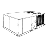
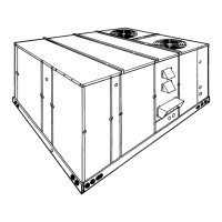
UNIT DIMENSIONS - D*CG180 & 240 UNITS
1235 (48-5/8") (180)
1337 (52-5/8") (240)
3181 (125-1/4") (180)
3561 (136-1/4") (240)
616 (24-1/4") (180)
895 (35-1/4") (240)
HOLE
OPENING
DIAMETER*
(in. / mm)
USED FOR
A
1-1/8 / 29 KO
Control Wiring
Front
3/4 NPS / 19 (Fem.) Bottom
B
3-5/8 / 92 KO
Power Wiring
Front
3 NPS / 76 (Fem.) Bottom
C 2-3/8 / 60 KO Gas Piping (Front)
D 1-11/16 / 43 Hole Gas Piping (Bottom)**
*KO denotes Knockout facility.
**Opening in the bottom of the unit can be located by the slice in the insulation.
UTILITIES ENTRY DATA
CLEARANCES (mm / in. )
Front
1
914 / 36
Back
610 / 24 (Less Economizer)
1245 / 49 (With Economizer)
Left Side (Filter Access)
610 / 24 (Less Economizer)
1372 / 54 (With Economizer)
Right Side (Outdoor Coil) 914 / 36
Below Unit
2
0 / 0
Above Unit
3
1829 / 72 with 914 / 36 maximum
Horizontal Overhang
(For Outdoor Air Discharge)
1
Locate unit so that the vent air outlet hoods are at least:
• 0.9 meter (3 ft) above any forced air inlet located within 3.0m (10 ft) horizontal
(excluding those integral to the unit).
• 1.2 meters (4 ft) below, 1.2m (4 ft.) horizontal from, or 0.31m(1 ft) above any door
or gravity air inlet into the building.
• 1.2 meters (4 ft) from electric meters, gas meters, regulators and relief equipment.
2
Units may be installed on combustible surfaces capable of continuous exposure to
temperatures of 92°C (197°F), and intermittent exposure to temperatures of 124°C (255°F).
3
Units must be installed outdoors. Overhanging structures or shrubs should not
obstruct the outdoor air discharge outlet.
NOTE: A 25mm (1 in.) clearance must be provided between any combustible material and the
supply air ductwork for a distance of 0.9m (3 ft) from the unit.
The products of combustion must not be allowed to accumulate within a confined space
and recirculate.
All dimensions are in millimeters and inches,
unless otherwise specified. They are subject to
change without notice. Certified dimensions
will be provided upon request.
530.26-TG3YI
16 Unitary Products Group