EasyManua.ls Logo

York TIWM006B21S User Manual

York TIWM006B21S
52 pages
To Next Page IconTo Next Page
Page #1 background imageLoading...
Page #1 background image
P5417052
Installation
and
Maintenance
Manual
INVERTER-DRIVEN
MULTI-SPLIT SYSTEM
HEAT PUMP
AIR CONDITIONERS
Type Model
Wall Mount
TIWM006B21S
TIWM008B21S
TIWM012B21S
TIWM015B21S
TIWM018B21S
TIWM024B21S
TIWM030B21S
IMPORTANT:
READ AND UNDERSTAND
THIS MANUAL BEFORE
INSTALLING THIS HEAT
PUMP AIR CONDITIONER.
KEEP THIS MANUAL FOR
FUTURE REFERENCE.

Other manuals for York TIWM006B21S

Question and Answer IconNeed help?

Do you have a question about the York TIWM006B21S and is the answer not in the manual?

York TIWM006B21S Specifications

General IconGeneral
Voltage115V
Power Supply115V/60Hz
Noise Level52 dB
Cooling Capacity6, 000 BTU/h
RefrigerantR32

Summary

Introduction

Safety Instructions

Signal Words

Explains the meaning of WARNING, CAUTION, and NOTICE indicators.

General Precautions

Provides essential safety guidelines for installation and operation.

Installation Precautions

Refrigerant Precautions

Electrical Precautions

Electrical Installation

Before Installation

Combination of Outdoor Unit and Indoor Unit

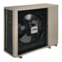
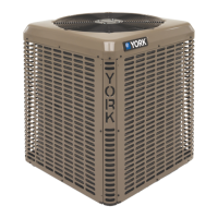
Guides on selecting compatible indoor and outdoor units for optimal capacity.

Transportation and Handling

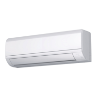
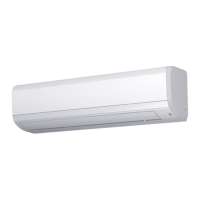
Provides instructions for safely moving and handling the indoor unit.

Factory-Supplied Accessories

Lists and describes the accessories included with the indoor unit.

Necessary Tools and Instrument List for Installation

Installation Location

Installation Work

Installation

Details the dimensions and placement for mounting the indoor unit.

Working Procedure

Outlines the step-by-step process for installing the indoor unit.

Mounting Plate onto Wall

Mounting Indoor Unit between Studs

Mounting Indoor Unit onto a Poured Concrete Wall or Concrete Block Wall

Removing Lower Right Corner Cover

Mounting Indoor Units

Removing Flat Panel

Position of Piping Connection

Refrigerant Piping Work

Piping Materials

Details the types and sizes of piping materials required for the system.

Piping Connections

Explains the procedures for performing flaring and connecting refrigerant pipes.

Condensate Piping

Connecting Condensate Piping

Provides instructions for connecting the condensate drain piping.

Electrical Wiring

General Check

Outlines initial checks for electrical components and power supply.

Electrical Wiring Capacity

Specifies requirements for wire sizes, GFCI, and main switches.

Electrical Wiring for Indoor Unit

Details the specific wiring connections for the indoor unit's terminal blocks.

Position of Electrical Wiring Connection

Illustrates wiring connection points and provides torque specifications.

Conduit Connection

DIP Switch Settings

Unit No. Setting

Explains how to set the indoor unit number for system configuration.

Capacity Code Setting (DSW3)

Describes the setting for the indoor unit's capacity code.

Refrigerant Cycle No. Setting (RSW2 & DSW5)

Details how to set the refrigerant cycle number for the unit.

Fuse Recovery (DSW7)

Instructions for recovering the unit after a fuse blow.

Optional Function Setting (DSW2)

Settings for optional functions like identifying units installed side by side.

Wired Controller Setting (SW2)

How to set the DIP switch for wired controller operation.

Function Selection by Wired Controller

Setback Operation

Test Run

Test Run with Wired Controller

Procedure for performing a test run using a wired controller.

Test Run with Wireless Controller

Procedure for performing a test run using a wireless controller.

Alarm Code

Related product manuals