356486-UUM-J-1211
_WARNING
FIRE OR EXPLOSION HAZARD
This furnace is designed and approved for use with Natural Gas
and (LP) Propane Gas ONLY. DO NOT BURN ANY LIQUID FUEL
OR SOLID FUEL IN THIS FURNACE.
Burning any unapproved fuel will result in damage to the furnace
heat exchanger, which could result in Fire, Personal Injury, and/or
Property Damage.
SECTION I1: INSTRUCTIONS FOR
EXAMINING THE FURNACE
INSTALLATION
It is the owner's responsibility to ensure that an annual inspection of the
entire heating portion of the unit is made by a qualified service agency.
Examine the furnace as outlined below in steps "1 - 8" before each
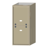
heating season. Use Figures 1 - 6 for visual reference.
Silicone
Tube
Induced
Dra_ Motor
Switch
Limit
Switch
Electrical
Junction
Box
Sensor
Switch
Blower
o
Vent Pipe
Flue Collar
Induced Draft
Assembly
Ignitor
Safety Switch
Manifold Pipe
Control Board
Capacitor
(Not used on all models)
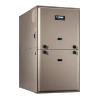
Power Factor
Choke
Not used on
models)
Manifold Switch
Sensor
Ignitor Limit Switch
Gas Valve Vent Pipe
Electrical Pressure Switch
Box Manifold Draft
Assembly
Condensate Pan
Tube
Safety Control Board
)acitor
Switch (Not used onall models)
Power Factor
Choke
(Not used on
all models)
FIGURE 1: Component Location - 80% Single & Two Stage Models FIGURE 2: Component Location - 95% Single & 96% Two Stage Models
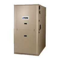
Silicone
Induced
Pressure
Sensor
Limit Switch
Electrical
Junction Box
Flame
Sensor
Safety
Door Switch
Flue
Collar
Pressure
Switch
Induced Draft
Assembly
Gas Valve
Ignitor
_)_ Safety Switch
Manifold
Pipe
Control
Board
Capacitor
PSC MOTOR
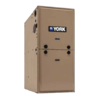
Silicone
Tube _
Induced
Draft Motor_
Pressure
Sensor
Limit Switch J
Electrical J
Junction Box
Flame _
Sensor
Safety _
Door Switch
Blower --I
Transformer _
ECM MOTOR
Flue
Collar
Pressure
Induced Draft
Assembly
Valve
4_- Ignitor
Rollout
Safety Switch
Manifold
Pipe
Control
Board
Choke
(Not used on
all models)
FIGURE 3: Component Location - 80% Modulating PSC Models FIGURE 4: Component Location - 80% Modulating ECM Models
2 Johnson Controls Unitary Products
 Loading...