5168274-BIM-I-1121
Johnson Controls Ducted Systems 9
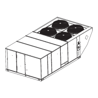
Figure 7: XA-20 Unit Dimensions Front View
NOTE: All entry holes should be field sealed to prevent rain water
entry into the building.
Table 3: XA-15, XA-20 Unit Accessory Weights
Unit Accessory
Weight (lbs.)
Shipping Operating
Economizer 165 160
Power Exhaust 90 85
Electric Heat
1
1. Weight given is for the maximum heater size available
(72KW).
40 40
Double Wall
2
2. Available on XA-20 only.
260 260
Motorized Damper 150 150
Barometric Damper 50 45
Econ./Motorized Damper Rain Hood 60 55
Econ./Power Exhaust Rain Hood 95 90
Wood Skid 220 220
Roof Curb 190 185
Utilities Entry
Hole
Opening Size
Diameter
Used For
A
1-1/8” KO
Control Wiring
Front
3/4” NPS (Fem.) Bottom
B
3-5/8” KO
Power Wiring
Front
3” NPS (Fem.) Bottom
6-7/8
(A) CONTROL WIRING
ENTRY
COIL
GUARD
KIT
CONDENSER
COILS
(B) POWER
WIRING ENTRY
5
43-3/4
9-3/4
35
5-7/8
136-1/4
DOT PLUG
(For pressure
drop reading)
BLOWER
COMPARTMENT
ACCESS
(Auxillary)
CONTROL BOX
ACCESS
BLOWER MOTOR
ACCESS
BLOWER
ACCESS
52-5/8
180-19/32
COMPRESSOR ACCESS
DISCONNECT
SWITCH
LOCATION
ECONOMIZER / MOTORIZED DAMPER
FIXED OUTDOOR INTAKE AIR AND
POWER EXHAUST RAIN HOODS
92
35-1/4
33
2-3/4
3-3/4
(B) POWER WIRING
ENTRY
BOTTOM SUPPLY
AND RETURN
AIR OPENINGS
(See Note)
(A) CONTROL WIRING
ENTRY
21-1/2
UNIT BASE RAILS
Shown separately to illustrate
Bottom Duct openings. Power
location.
RETURN
AIR
NOTE:
For curb mounted units, refer to the curb hanger
dimensions of the curb for proper size of the
supply and return air duct connections.
12-1/2
9-1/4
8-1/8
9-3/4
SUPPLY
AIR
14-3/4
OPTIONAL
ELECTRIC HEAT
ACCESS
 Loading...