YORK INTERNATIONAL
10
FORM 150.62-NM7 (103)
29224(RIG)A
To ensure warranty coverage, this
equip ment must be commissioned
and ser viced by an authorized YORK
ser vice mechanic or a qualifi ed service
per son ex pe ri enced in chiller in stal -
la tion. In stal la tion must comply with
all ap pli ca ble codes, particularly in
regard to electrical wiring and other
safety el e ments such as relief valves,
HP cutout settings, de sign working
pres sures, and ven ti la tion re quire -
ments consistent with the amount and
type of re frig er ant charge.
Lethal voltages exist within the con trol
panels. Be fore servicing, open and tag
all dis con nect switch es.
INSTALLATION CHECK LIST
The following items, 1 through 5, must be checked be-
fore plac ing the units in operation.
1. Inspect the unit for shipping damage.
2. Rig unit using spreader bars.
3. Open the unit only to install water piping system.
Do not remove protective covers from water con-
nec tions until piping is ready for attachment. Check
water pip ing to ensure cleanliness.
4. Pipe unit using good piping practice (see ASHRAE
handbook section 215 and 195).
5. Check to see that the unit is installed and operated
within limitations (Refer to LIM I TA TIONS).
The following pages outline detailed pro ce dures to be
followed to install and start-up the chiller.
HANDLING
These units are shipped as completely assembled units
containing full operating charge, and care should be
tak en to avoid damage due to rough handling.
INSTALLATION
INSPECTION
Immediately upon receiving the unit, it should be in-
spect ed for possible damage which may have oc curred
during tran sit. If damage is evident, it should be noted in
the car ri er’s freight bill. A writ ten request for in spec tion
by the car ri er’s agent should be made at once. See
“In struc tion” man u al, Form 50.15-NM for more in for -
ma tion and details.
LOCATION AND CLEARANCES
These units are designed for outdoor installations on
ground level, rooftop, or beside a building. Location
should be selected for minimum sun exposure and to
insure adequate supply of fresh air for the condenser.
The units must be installed with suffi cient clearances
for air en trance to the condenser coil, for air discharge
away from the condenser, and for servicing access.
In installations where winter operation is intended and
snow accumulations are ex pect ed, ad di tion al height
must be provided to ensure normal condenser air
fl ow.
Clearances are listed under “Notes” in the “DI MEN -
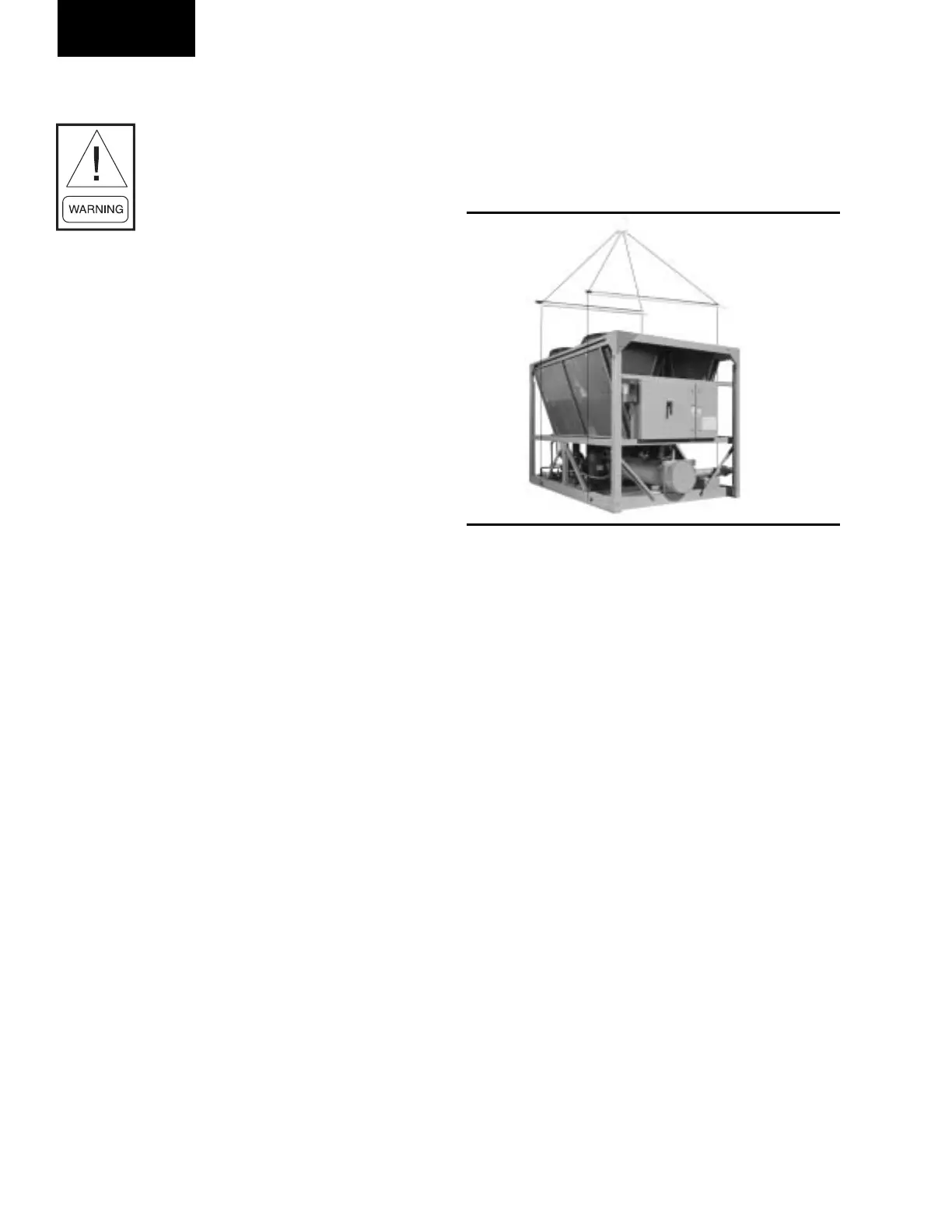
The unit should be lifted by inserting hooks through
the holes provided in unit base rails. Spreader bars
should be used to avoid crushing the unit frame rails
with the lifting chains. See below.
Installation
 Loading...


