EasyManua.ls Logo

York YHKJXH018BAM--FX User Manual

York YHKJXH018BAM--FX
161 pages
To Next Page IconTo Next Page
Page #1 background imageLoading...
Page #1 background image
Commercial Air Conditioning
SERVICE MANUAL
Models
Inverter R410a 50/60HZ
Indoor:
YHKJXH012BAM--FX YHKJXH018BAM--FX
YHKJXH024BAR--FX YHKJXH028BAR--FX
YHKJXH036BAR--FX YHKJXH048BAR--FX
YHKJXH048BAR--FX YHKJXH060BAR--FX
YHFJXH012BAM--FX YHFJXH018BAM--FX
YHFJXH024BAR--FX YHFJXH028BAR--FX
YHFJXH036BAR--FX YHFJXH048BAR--FX
YHFJXH048BAR--FX YHFJXH060BAR--FX
YHDJXH012BAM--GX YHDJXH018BAM--GX
YHDJXH024BAR--GX YHEJXH024BAR--GX
YHEJXH028BAR--GX YHEJXH036BAR--GX
YHEJXH048BAR--GX YHEJXH048BAR--GX
YHGJXH048BAR--GX YHGJXH048BAR--GX
YHGJXH060BAR--GX
Outdoor:
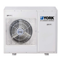
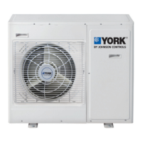
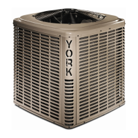
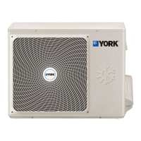
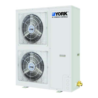
YHUJYH024BAR-A-X
YHUJYH028BAR-A-X
YHUJYH036BAR-A-X
YHUJYH048BAR-A-X
YHUJYH048BAS-A-X
YHUJYH060BAS-A-X
1
Question and Answer IconNeed help?

Do you have a question about the York YHKJXH018BAM--FX and is the answer not in the manual?

York YHKJXH018BAM--FX Specifications

General IconGeneral
Cooling Capacity18, 000 BTU/h
SEER16
Power Supply208/230V, 1Ph, 60Hz
RefrigerantR-410A
TypeSplit System
Operating Temperature (Cooling)18-43 °C
Operating Temperature (Heating)-7°C to 24°C

Summary

1. Description of products & features

Brief Introduction to T1 Working Condition

Provides an overview of the T1 working condition for air conditioners.

Operating Range of Air Conditioners

Details the working temperature ranges for cooling and heating operations.

Product Features

Highlights key features and technologies of the air conditioning units.

2. Specification

3. Dimension

4. Piping and Wiring Installation

Safety Precautions for Installation

Crucial safety guidelines to prevent hazards during installation and handling of units.

Preparation Before Installation

Essential checks, tools, materials, and air tightness tests before proceeding with installation.

Unit Installation Procedures

Step-by-step guide for unit installation, including placement, piping, wiring, and vacuuming.

5. PCB Photo, Wiring Diagram, and Function Description

Outdoor Unit Components and Diagrams

Photos and diagrams of outdoor unit PCBs, modules, and wiring.

3. Main Control Functions

Refrigerant Circuit and Component Control

Diagrams illustrating refrigerant flow and control of key components like EEV and 4-way valve.

Operational Logic and Protection Mechanisms

Details on defrosting, frequency control, oil return, and abnormal operation handling.

6. Diagnostic Codes and Troubleshooting

Outdoor Unit Diagnostic Codes

Lists fault codes for the outdoor unit with corresponding analysis and diagnosis.

Indoor Unit Diagnostic Codes

Lists fault codes for the indoor unit with corresponding analysis and diagnosis.

Troubleshooting Flowcharts

Provides step-by-step diagnostic guides and flowcharts for resolving common unit issues.

7. Outdoor Performance Curves

8. Indoor Air Velocity and Temperature Distribution Curves

Cooling Air Velocity and Temperature Distribution

Visual representation of air flow patterns and temperature distribution during cooling operation.

9. Air Flow and Static Pressure Chart

10. Noise Level

Indoor Unit Noise Levels

Data on noise levels for different indoor unit types across various frequencies.

11. Sensor Characteristics

Parts and Functions

Remote Controller Operation

Explains the functions and usage of the remote controller for various modes and settings.

Wired Controller Functions

Details on wired controller operation, settings, and malfunction checks.
Related product manuals