EasyManua.ls Logo

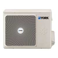
York YHKMXH009BARR-FX User Manual

York YHKMXH009BARR-FX
137 pages
To Next Page IconTo Next Page
Page #1 background imageLoading...
Page #1 background image
Commercial Air Conditioning
SERVICE MANUAL
Models
Outdoor:
YJU3YH019BARRA-X
YJU4YH025BARRA-X
YJU4YH030BARRA-X
YJU5YH034BARRA-X
YHKMXH009BARR-FX
YHKMXH012BARR-FX
YHKMXH018BARR-FX
YHKMXH024BARR-FX
YHFMXH012BARR-FX
YHFMXH018BARR-FX
YHFMXH024BARR-FX
YHDMXH009BARR-FX
YHDMXH012BARR-FX
YHDMXH018BARR-FX
YHDMXH024BARR-FX
Indoor:
MULTI Split series
___________________________________________________________________________________

Questions and Answers:

York YHKMXH009BARR-FX Specifications

General IconGeneral
Model NumberYHKMXH009BARR-FX
Cooling Capacity9, 000 BTU/h
RefrigerantR410A
Power Supply220-240V, 50Hz
Noise Level (Outdoor Unit)50 dB

Summary

1. Description of products & features

1.3 Product features

Highlights key features of the product, like DC inverter technology and R410a refrigerant.

2. Specifications

4. Pipe and wiring installation

4.2. Wiring connection

Illustrates the wiring connections between indoor and outdoor units for various models.

4.4 Outdoor installation

Provides guidelines and considerations for the outdoor unit installation.

Refrigerant piping work

4. Purging and checking gas leakage

Procedure for purging and checking for gas leakage.

Electrical Wiring

TEST RUNNING

4.Trial operation

5. PCB photo,Wiring diagram and function description

5.1.2. Wiring diagram

Provides wiring diagrams for outdoor units, showing connections for various components.

3. Main control functions

3.6 Control of defrosting in heating

Describes the control logic for defrosting the outdoor heat exchanger during heating.

3.8 Frequency control when there is CT over current protection

Details frequency control adjustments for CT over current protection.

3.9 High pressure protection

Explains the system's response to high-pressure conditions.

3.10 Low pressure protection

Describes the system's response to low-pressure conditions.

3.11 Oil return operation control

Explains the automatic oil return operation control procedures.

5.2 Indoor unit

5.2.2. Indoor Wiring Diagram

Provides the wiring diagram for the indoor unit.

5.2.5. Electrical Control Functions

Dip Switch and Controller Settings

Explains dip switch functions and wiring controller addresses for indoor units.

12. Controller functions

Related product manuals