Do you have a question about the York YLAA0285SE and is the answer not in the manual?
Provides an overview of YORK YLAA Air-Cooled Scroll Chillers and their applications.
Details the warranty terms, coverage period, and conditions for the chiller equipment.
Outlines design standards and compliance with safety codes and regulations.
Defines the primary responsibilities of personnel operating or working on the machinery.
Explains the meaning of hazard alert terms (DANGER, WARNING, CAUTION, NOTE) used in the document.
Discusses the consequences of using the equipment outside its intended application or parameters.
Provides crucial safety instructions for electrical work, including grounding and power isolation.
Highlights specific hazards like sharp edges, refrigerants, and emergency shutdown procedures.
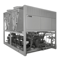
Introduces the YLAA Air-Cooled Scroll Chillers for HVAC applications.
Provides a high-level overview of the chiller's main systems and components.
Details the hermetic scroll compressors and the direct expansion evaporator design.
Details condenser coils, fans, motors, and the control panel's display and keypad functions.
Describes the ON/OFF switch, HIGH AMBIENT KIT, BAS interface, and power panel components.
Lists and describes various accessories and options available for the chiller unit.
Details power connection options, ambient kits, language display, and compressor/piping options.
Details options like Hot Gas By-Pass, Flanges, Flow Switches, Hydro-Kits, and condenser/cabinet protection.
Covers options for louvred panels, coil guards, sound attenuation, and vibration isolators.
Identifies key unit components through diagrams and labels.
Explains the nomenclature and structure of the unit's Product Identification Number.
Provides guidelines for unit delivery, storage, and precautions to prevent damage.
Details the steps for inspecting the unit for shipping damage upon receipt.
Offers instructions and warnings for safely moving and lifting the chiller unit.
Provides detailed instructions and diagrams for proper rigging and lifting arrangements.
Covers inspection, handling, and essential checks before unit operation.
Provides guidance on selecting suitable installation sites and required clearances.
Details foundation requirements for ground, rooftop, and noise-sensitive locations, including isolator info.
Covers chilled liquid piping, compressor mounting, and remote cooler options.
Suggests pipework arrangements and considerations for the chilled liquid system.
Provides recommendations for duct work connections and general wiring guidelines.
Details alarm status, remote start/stop, temp reset, load limit, and flow switch inputs/outputs.
Details options for single-point electrical supply connections including terminal blocks and circuit breakers.
Describes the wiring for user control inputs, including remote reset and flow switch connections.
Describes the wiring for user control outputs, including alarm and run status signals.
Specifies operational limits for temperatures, flows, and voltage, including important CAUTION notes.
Provides pressure drop curves for heat exchangers and glycol correction factors.
Details physical specifications for standard efficiency YLAA models, including dimensions and weights.
Details physical specifications for high efficiency YLAA models, including dimensions and weights.
Provides details on micropanel power supply, voltage ranges, and electrical data tables.
Explains electrical notation, legends, and important notes related to wiring and circuit protection.
Introduces elementary and connection wiring diagrams for YLAA0195 models.
Continues elementary wiring diagrams for YLAA0195 models across multiple sheets.
Introduces and continues connection wiring diagrams for YLAA0195 models.
Provides elementary wiring diagrams for YLAA0220 to YLAA0515 models across multiple sheets.
Introduces and continues connection wiring diagrams for YLAA0220 to YLAA0515 models.
Shows wiring diagrams for different single-point power supply options.
Provides the wiring diagram specifically for dual pump configurations.
Provides detailed dimensions in English for various YLAA models.
Specifies required clearances for all models to ensure proper operation and maintenance access.
Contains cross-reference data for spring, seismic, and Duralene isolators, including dimensions and capacities.
States that commissioning must be performed by authorized personnel and outlines the process.
Lists essential checks to perform with unit power OFF: inspections, refrigerant charge, and valve checks.
Covers checks for compressor oil, fans, electrical isolation, control panel, power connections, and grounding.
Details checks after applying power: switch settings, compressor heaters, water system, flow switch, and sensors.
Provides a comprehensive checklist for pre-startup and startup procedures, including unit, compressor, and panel checks.
Details procedures for calculating and verifying subcooling and checking suction superheat.
Instructions for performing a leak check on compressors, fittings, and piping.
Describes the step-by-step sequence of unit operation, including compressor, fan, and system staging.
Introduces the microprocessor-based control system and its four basic components.
Explains the roles of the IPU II board (controller) and I/O board (inputs/outputs) in system operation.
Describes the on-board power supply, display, keypad functions, battery backup, transformer, and compressor programming.
Explains how to use the STATUS key to view operating status and fault messages.
Details various general status messages like UNIT SWITCH OFF, REMOTE CONTROLLED SHUTDOWN, and FLOW SWITCH OPEN.
Describes messages related to cooling load, compressor status, timers, and pressure limiting.
Explains safety messages for system and unit faults, detailing HIGH DSCH PRES and LOW SUCT PRES.
Covers unit safety faults (LOW AMBIENT TEMP, LOW LIQUID TEMP) and warnings (LOW BATTERY, INCORRECT UNIT TYPE).
Provides a quick reference list for various status key messages, categorized by general, system, and safety/warning types.
Explains how to use the DISPLAY/PRINT keys to retrieve system and unit information.
Details how to access and scroll through system operating parameters using the OPER DATA key.
Describes displays for suction/discharge pressure, cooling demand, and temperature error.
Explains displays showing accumulated compressor running hours and starts for each system.
Describes various unit status displays including evaporator heater, pump status, actual amps, and fan stage.
Provides a quick reference table for accessing various operation data screens via the OPER DATA key.
Explains how to use the PRINT key to obtain real-time or history printouts of system data.
Describes how to access and scroll through stored safety shutdown information and obtain printouts.
Explains displays for control modes (Leaving/Return Liquid), Lead/Lag, Fan Control, and various setpoints.
Describes various unit status displays including evaporator heater, pump status, actual amps, and software version.
Explains the function of the ENTRY keys (UP, DOWN, ENTER/ADV) for navigating and changing programmed values.
Details how to use the SETPOINTS keys to adjust cooling setpoints and ranges for different control modes.
Describes how to program the seven-day schedule and holiday settings.
Table listing programmable limits and default values for cooling setpoints and temperature reset.
Details how to program parameters like pressure cutouts, ambient limits, anti-recycle timer, and fan control.
Provides formulas and examples for calculating and programming system trip voltages.
Table detailing programmable limits and default values for various program key settings.
Provides a quick reference chart for navigating setpoints using the control panel keys.
Explains how to use the UNIT keys, particularly OPTIONS key for configuring unit settings like language and system switches.
Covers options for ambient control type and unit control modes (return/leaving liquid).
Explains lead/lag control types and options for displaying units in Imperial or SI units.
Details options for condenser fan control, manual override, current feedback, and power fail restart.
Details options for refrigerant type and expansion valve type (thermostatic/electronic).
Explains procedures for updating software via flash card and selecting remote temperature reset inputs.
Describes options for onboard pump control and selecting pump configurations.
Explains how to view and set the current day, time, and date using the CLOCK key.
Provides a quick reference chart for programming options accessible via the UNIT keys.
Describes the conditions required to initiate the chiller's start sequence and capacity control functions.
Explains anticipatory controls to prevent low-pressure cutouts by limiting loading.
Details controls that unload the system before high discharge pressure safety limits are reached.
Explains how the chiller maintains leaving chilled liquid temperature by staging compressors.
Describes how compressors are sequenced within circuits and how lead/lag systems equalize run hours.
Explains how the setpoint can be temporarily adjusted to prevent excessive compressor cycling.
Explains return chilled liquid control for staging compressors based on load, and provides compressor staging tables.
Table providing sample compressor staging data for return water control.
Details lead/lag and compressor sequencing for return chilled liquid systems to equalize run hours.
Table outlining return chilled liquid control steps for 4 compressors.
Table detailing return chilled liquid control steps, including lead/lag system assignments.
Explains the function of anti-recycle timers for preventing short cycling and anti-coincidence timers.
Describes the control of the evaporator pump and YORK Hydro Kit pump.
Details the control of the evaporator heater based on ambient temperature and the pumpdown feature.
Explains condenser fan control based on discharge pressure and programmable settings.
Table detailing standard condenser fan control logic using discharge pressure for 2, 3, or 4 fans per system.
Table detailing standard condenser fan control logic using discharge pressure for 5 or 6 fans per system.
Explains the load limiting feature to prevent the unit from exceeding desired values, with tables for compressor limits.
Table showing compressor operation limits based on the number of compressors and load limiting stages.
Describes how compressor run status and alarm status are indicated via contacts.
Details how BAS/EMS can reset the chilled liquid setpoint using voltage or current signals.
Instructions on how to clear the unit's history buffers, with a warning about data loss.
Explains Service Mode functionality for enabling/disabling outputs and viewing/modifying parameters.
Guides on configuring settings like data logging, soft start, refrigerant type, and expansion valve type.
Explains how to view analog and digital inputs to the microboard, including pressure and temperature sensor readings.
Provides reference tables for digital and analog inputs/outputs, detailing connection points and descriptions.
Illustrates the physical layout of the microboard, identifying key connectors and components.
Details how to check digital and analog inputs/outputs, focusing on voltage references and sensor connections.
Describes analog temperature inputs and their connections, including the outside air sensor.
Lists test points for entering and leaving chilled liquid sensors and their voltage correlations.
Explains analog pressure inputs, their connections, and formulas for calculating voltage outputs from transducers.
Provides instructions for installing an optional printer, including required parts and assembly.
Addresses issues like no display, flow switch problems, and low suction pressure faults.
Highlights key aspects of maintenance, including compressor oil checks, oil analysis, and component inspections.
Details procedures for checking compressor oil levels and performing oil analysis for contamination.
Covers maintenance for condenser fan motors and condenser coils, emphasizing cleaning.
Emphasizes regular checks of operating parameters and information on the on-board battery backup.
Provides specific instructions and DO NOTs for cleaning microchannel coils to prevent damage.
Explains how to read and modify chiller data using serial communication protocols.
Lists analog and binary write/read points for BACnet, Modbus, and YorkTalk 2, including register addresses.
Specifies required setup values for BACnet MS/TP, Modbus RTU, and YorkTalk 2 protocols.
Explains how the unit receives and transmits data using YorkTalk 2 communication.
Provides charts for converting temperatures between Fahrenheit and Celsius, and pressures between units.
A chart showing the relationship between R410A pressure and temperature.
| Model | YLAA0285SE |
|---|---|
| Type | Air-Cooled Scroll Chiller |
| Cooling Capacity | 285 Tons |
| Refrigerant | R-410A |
| Compressor Type | Scroll |
| Voltage | 460V |
| Phase | 3 |
| Frequency | 60 Hz |
| Sound Power Level | 85 dBA |
| Weight | 14500 lbs |