EasyManua.ls Logo

York YLAA0260HE - User Manual

York YLAA0260HE
206 pages
To Next Page IconTo Next Page
Loading...
YLAA0195 - YLAA0515
AIR-COOLED SCROLL CHILLERS
WITH MICROCHANNEL CONDENSER COILS
STYLE A (50 HZ)
57 - 142 TON
Products are produced at a
f a c i l i t y wh o s e q u a l i t y -
management systems are
ISO9001 certified.
R-410A
Issue Date:
October 5, 2020
035-21911-001
AIR-COOLED SCROLL CHILLER
INSTALLATION, OPERATION, MAINTENANCE
Supersedes 150.72-NM3 (811) Form 150.72-NM3 (1020)

Table of Contents

Question and Answer IconNeed help?

Do you have a question about the York YLAA0260HE and is the answer not in the manual?

York YLAA0260HE Specifications

General IconGeneral
ModelYLAA0260HE
CategoryChiller
Cooling Capacity260 Tons
Compressor TypeScroll
RefrigerantR-410A
Number of Circuits2
Number of Compressors4
Leaving Water Temperature Range40°F to 60°F
Voltage460V

Summary

Air-Cooled Scroll Chiller Installation, Operation, Maintenance

General Safety Guidelines

Section 1: General Chiller Information and Safety

Safety and Quality Standards Compliance

Outlines the safety codes and standards the chillers comply with, including ISO and ASHRAE.

Section 2: Product Description

Introduction to YORK YLAA Chillers

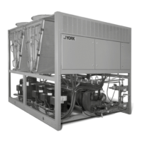
Describes the self-contained, outdoor-designed YLAA chillers and their components for air conditioning applications.

General System Description Overview

Details the main system components including compressors, the cooler (evaporator), and condenser specifications.

Accessories and Options for YLAA Chillers

Unit Components Overview

Power Panel Components Overview

Power Panel Components Identification

Details components within the power panel, such as fan contactors, compressor contactors, and overloads.

Product Identification Number (PIN) System

Basic Unit Nomenclature Breakdown

Explains the structure and meaning of the YLAA unit's Product Identification Number (PIN) for model identification.

Refrigerant Flow Diagram

YLAA Refrigerant Circuit Diagram

Illustrates the refrigerant circuit, including key components, sensors, and transducers for YLAA units.

Process and Instrumentation Diagram (P&ID)

P&ID Explanation and Component Key

Provides a diagram of the process and instrumentation, with a key for components and control functions.

Section 3: Handling and Storage Procedures

Moving and Lifting the Chiller Unit Safely

Provides instructions and warnings for safely moving and lifting the chiller unit, emphasizing the use of lifting eyes.

Section 4: Installation Procedures

Location Selection and Installation Clearances

Guides site selection for outdoor installation, considering air supply, sound, and necessary clearances.

Single-Point Supply Connection Diagrams

User Control Wiring Inputs Diagram

User Control Wiring Outputs Diagram

Section 5: Technical Data

Operational Limitations and Voltage Data

Provides temperature/flow data, voltage limitations, and notes on evaporator protection and optional kits.

Physical Data for Standard Efficiency YLAA Models

Physical Data for High Efficiency YLAA Models

Wiring Diagrams: YLAA0195 Elementary Diagrams

Elementary Wiring Diagrams - YLAA0195 Sheets 1-9

Provides detailed elementary wiring diagrams for YLAA0195 units, covering multiple sheets for circuit representation.

Wiring Diagrams: YLAA0195 Connection Diagrams

Connection Wiring Diagrams - YLAA0195 Sheets 1-7

Offers connection wiring diagrams for YLAA0195 units, detailing connections between components and terminal blocks.

Wiring Diagrams: YLAA0220-YLAA0515 Elementary Diagrams

Elementary Wiring Diagrams - YLAA0220-YLAA0515 Sheets 1-5

Contains elementary wiring diagrams for YLAA0220-YLAA0515 units, covering multiple sheets for circuit details.

Wiring Diagrams: YLAA0220-YLAA0515 Connection Diagrams

Power Panel Connection Diagrams - YLAA0220-YLAA0515 Sheet 1

Shows power panel connection diagrams for YLAA0220-YLAA0515 units, illustrating terminal block and component wiring.

Micropanel Connections - YLAA0220-YLAA0515

Micropanel Connections Details

Details micropanel connections for YLAA0220-YLAA0515 units, illustrating connector and terminal mapping.

Power Options Connection Diagrams - YLAA0220-YLAA0515

Power Options Connection Diagrams Details

Illustrates power options connection diagrams for YLAA0220-YLAA0515 units, showing transformer and circuit configurations.

Compressor Wiring Diagrams - YLAA0220-YLAA0515

Compressor Wiring Diagrams Details

Provides compressor wiring diagrams for YLAA0220-YLAA0515 units, detailing motor and sensor connections.

Condenser Fan Mapping and Sequencing Diagrams - YLAA0220-YLAA0515

Condenser Fan Mapping and Sequencing Details

Shows condenser fan mapping and sequencing diagrams for YLAA0220-YLAA0515 units, illustrating fan control logic.

Dimensions for YLAA0195 HE Model

Dimensions for YLAA0220 HE, 0260 HE, 0285 SE, & 320 SE Models

Dimensions for YLAA0300 HE, YLAA0360 SE, YLAA0400 SE Models

Dimensions for YLAA0435 SE (ENGLISH)

Dimensions for YLAA0350 HE (ENGLISH)

Dimensions for YLAA0390 HE, YLAA0485 SE (ENGLISH)

Dimensions for YLAA0440 HE (ENGLISH)

Dimensions for YLAA0455 HE (ENGLISH)

Dimensions for YLAA0515 HE (ENGLISH)

Weight Distribution and Isolator Mounting Positions

Isolator Data: Spring Isolator Cross-Reference

Seismic Isolator Cross-Reference and Specifications

Duralene Isolator Cross-Reference and Dimensions

Section 6: Commissioning Procedures

Commissioning Overview and Preparation (Power Off)

Specifies authorized personnel for commissioning and details pre-startup checks with unit power off.

Equipment Pre-Startup & Startup Checklist

Pre-Startup System Checks (No Power)

Lists essential checks before initial start-up, covering piping, refrigerant, oil level, and pump operation.

Superheat, Subcooling, and Leak Checking

Checking Superheat and Subcooling Levels

Explains how to calculate and verify superheat and subcooling for system optimization and safety.

Unit Operating Sequence Description

Section 7: Unit Controls

YORK Millennium Control Center Overview

Introduces the microprocessor-based control system and its main components: IPU II, transformer, display, and keypad.

Status Key Messages and Unit Status Display

System Status Messages and Limiting Features

System and Unit Safety Fault Messages

System Safety Fault Messages Explained

Details fault messages related to system safeties like High Discharge Pressure and Low Suction Pressure cutouts.

Unit Safety Fault Messages Explained

Describes unit safeties such as Motor Protector/High Pressure Cutout Faults and their corresponding messages.

Motor Protector Faults and System Current Feedback

Unit Safety Faults and Warnings

Unit Safety Faults: Ambient, Liquid Temp, Voltage

Covers unit safeties related to low ambient temperature, low leaving chilled liquid temperature, and under voltage.

Status Key Messages Quick Reference

Categorization of Status Key Messages

Organizes status key messages into General, Fault, and Unit Safeties & Warning categories for quick reference.

Display;Print Keys and Operating Data Functionality

Operation Data Quick Reference List

Reference Table for Operation Data Screens

Provides a quick reference table listing all available operation data screens accessible via the OPER DATA key.

Print Key Functionality and History Access

Print Key Functionality and Data Printout

Explains how to obtain printouts of real-time data or history using the PRINT key and OPER DATA key.

History Key for Accessing Safety Shutdown Data

Describes how to access history buffers via the HISTORY key to view safety shutdown details and system conditions at fault.

Entry Keys for Programming and Navigation

Setpoints Keys for Programming Cooling Parameters

Program Key for Parameter Configuration

Setpoints Quick Reference List

Reference Chart for Setpoints Programming

Provides a quick reference chart for navigating setpoints via the Cooling Setpoints, Schedule/Advance Day, and Program keys.

Unit Keys for Options Configuration

Unit Keys Options Quick Reference List

Reference Chart for Unit Key Options Programming

Provides a quick reference chart for programming various unit options using the keypad, covering all configurable settings.

Section 8: Unit Operation

Capacity Control and Chiller Start Sequence

Explains the steps to initiate the chiller's start sequence, including pump and flow switch requirements.

Pressure Limit Controls (Suction and Discharge)

Details anticipatory controls that prevent low-pressure cutouts and limit discharge pressure to avoid safety limits.

Leaving Chilled Liquid Control Logic and Sequencing

Leaving Chilled Liquid Control Logic and Setpoints

Explains the logic for controlling leaving chilled liquid temperature, including setpoints, ranges, and compressor sequencing.

Return Chilled Liquid Control Strategy and Staging

Return Chilled Liquid Control Strategy and Staging

Details the return chilled liquid control strategy, compressor staging, and loading/unloading formulas.

Return Chilled Liquid System Lead;Lag Sequencing

Load Limiting and Compressor Operation Status

Load Limiting Feature and Compressor Operation Table

Describes load limiting functionality and provides a table showing compressor operation stages based on load.

BAS;EMS Temperature Reset via Signal

Section 9: Service and Troubleshooting

Clearing History Buffers and Entering Service Mode

Details how to clear history buffers and enter Service Mode for unit configuration and diagnostics.

Service Mode: Analog & Digital Inputs Viewing

Control Inputs;Outputs Quick Reference Tables

Microboard Layout Diagram and Component Identification

Analog Inputs - Pressure and Transducer Connections

Analog Inputs - Pressure and Transducer Connections

Explains analog pressure inputs, transducer connections, and provides formulas for voltage output verification.

Digital Outputs and I;O Board Relay Architecture

Optional Printer Installation Procedures

Troubleshooting Common Problems and Solutions

Panel Display and Unit Operation Troubleshooting

Addresses problems like no display or unit not operating, providing causes and solutions.

Flow Switch Permissive and Suction Pressure Fault Troubleshooting

Troubleshoots issues related to flow switch/remote stop permissive and low suction pressure faults.

Troubleshooting Low Suction, High Discharge, and Low Liquid Temp Faults

Troubleshooting MP;HPCO Faults, Compressor Start, and Cooling Issues

Section 10: Maintenance Procedures

Compressor Maintenance: Oil Level and Analysis

Details procedures for checking compressor oil level and performing oil analysis for system health.

Microchannel Coil Cleaning Procedure and Precautions

BACnet, Modbus, and YorkTalk 2 Communications Setup

Temperature and Pressure Conversion Charts

R410 A Pressure Temperature Chart

Related product manuals