JOHNSON CONTROLS
114
FORM 150.72-NM3 (1020)
ISSUE DATE 10/05/2020
SECTION 5 – TECHNICAL DATA
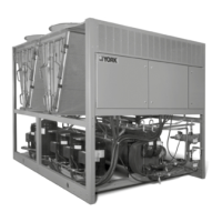
DIMENSIONS - YLAA0435SE (ENGLISH)
HOLES(TYP)
TOP VIEW
RIGHT VIEW
FRONT VIEW
POWER: SINGLE POINT SUPPLY WITH TERMINAL BLOCK
525
14012
VIEW B-B
BOTOM OF PANEL
B
B
749
TO CLR CONN
2242 BASE WIDTH
2261
2977
193
28 (TYP)
2077
81
1085
2393
498
588
3613
1006
588
2X 414
(2) RIGGING HOLES
EACH SIDE
ORIGIN
POWER ENTRY
8712 WIDE X 178 HIGH
8"
(WATER OUTLET)
8"
(WATER
INLET)
Y
C
G
X
861
FIG. 44 – DIMENSIONS (ENGLISH) YLAA0435SE (ENGLISH)
NOTE:
Placement on a level surface of free of obstructions
(including snow, for winter operation) or air circulation
ensures rated performance, reliable operation, and ease
of maintenance. Site restrictions may compromise
minimum clearances indicated below, resulting in
unpredictable airow patterns and possible diminished
performance. Johnson Controls’s unit controls will
optimize operation without nuisance high-pressure
safety cutouts; however, the system designer must
consider potential performance degradation. Access to
the unit control center assumes the unit is no higher than
on spring isolators. Recommended minimum clearances:
Side to wall – 6'; rear to wall – 6'; control panel to end
wall – 4'0''; top – no obstructions allowed; distance
between adjacent units – 10'. No more than one adjacent
wall may be higher than the unit.
 Loading...