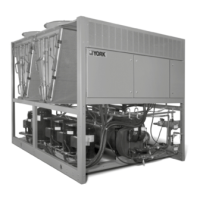
EasyManua.ls Logo

York YLAA0200 User Manual

York YLAA0200
206 pages
To Next Page IconTo Next Page
Page #1 background imageLoading...
Page #1 background image
YLAA0041 – YLAA0230
Air-Cooled Scroll Chillers
With Brazed Plate Heat Exchanger
Style B (60 HZ) 4–12 Fan
40 ton to 230 ton
140 kW to 800 kW
R-410A
Issue Date:
August 3, 2022
Air-Cooled Scroll Chiller
Installation, Operation,
Maintenance
Supersedes: 150.72-ICOM6 (221) Form 150.72-ICOM6 (822)
Products are produced at a
f aci lit y who s e qua l it y -
management systems are
ISO9001 certified.
035-23572-100

Table of Contents

Other manuals for York YLAA0200

Question and Answer IconNeed help?

Do you have a question about the York YLAA0200 and is the answer not in the manual?

York YLAA0200 Specifications

General IconGeneral
BrandYork
ModelYLAA0200
CategoryChiller
LanguageEnglish

Summary

SECTION 1 – GENERAL CHILLER INFORMATION AND SAFETY

WARRANTY

Details Johnson Controls' warranty terms, limitations, and conditions for equipment and materials.

SAFETY AND QUALITY

Information on chiller design standards, compliance with safety codes, and ISO 9002 accreditation.

MISUSE OF EQUIPMENT

Details on the unit's intended application and warnings against improper use or operation outside parameters.

Emergency Shutdown

Details on the unit's emergency shutdown feature via the control panel's Unit Switch.

SECTION 2 – PRODUCT DESCRIPTION

SECTION 4 – INSTALLATION

STARTUP/COMMISSIONING

Outline of detailed procedures required for chiller installation and initial start-up.

WIRING

Instructions for field wiring, including power wiring requirements and recommendations for conductor types.

SECTION 5 – TECHNICAL DATA

OPERATIONAL LIMITATIONS

Table detailing operational limitations for temperatures and flows for YLAA chillers.

ELECTRICAL DATA

Comprehensive electrical data including power supply, voltage ranges, and compressor heater specifications.

ELECTRICAL NOTES

Important notes and explanations regarding electrical installation, wiring, and component ratings.

ELECTRICAL NOTES AND LEGEND

Legend for electrical diagrams and notes on wiring practices, symbols, and component designations.

SECTION 6 – COMMISSIONING

PREPARATION – POWER OFF

Basic checks to perform with the unit's customer power switched OFF before proceeding.

Refrigerant Charge

Procedure for checking the refrigerant charge, ensuring pressure and leak integrity.

Charging Refrigerant

Step-by-step guide for charging refrigerant after vacuuming, including specific procedures for evaporator and system.

Power Connections

Check for correct customer power cable connections to terminal blocks or circuit breakers.

Grounding

Verification of unit's protective ground terminals and internal ground connections.

PREPARATION – POWER ON

Checks to perform after applying power to the chiller and turning on the panel circuit breaker.

COMMISSIONING THE PUMP VFD

Steps for commissioning the Variable Frequency Drive (VFD) for the pump, including parameter adjustments.

Programming the Drive

Instructions for accessing Service Mode to enable drive parameters and adjust settings.

PRE-STARTUP

Pre-startup checks to be performed with the unit powered OFF, focusing on physical and piping integrity.

START-UP CHECKLIST

Checklist for startup procedures, including power checks, setpoint verification, and compressor rotation.

SECTION 7 – UNIT CONTROLS

Safety Status Messages

Classification of safety faults causing system or unit shutdowns and their display messages.

System Safeties

Description of system safeties that cause individual system shutdowns and auto-reset behavior.

Unit Safeties

Explanation of unit safeties that shut down all compressors and auto-reset behavior.

Unit Fault Messages

Details on unit fault messages like LOW AMBIENT TEMP, LOW LIQUID TEMP, and 115VAC UNDER VOLTAGE.

Resetting System Lockout Faults

Procedure for manually resetting system lockout faults that occur after multiple consecutive errors.

Motor Protector/High Pressure Cutout Fault

Details on faults related to motor protector or high pressure cutout, affecting compressor and system operation.

Low Superheat Cutout (EEV Mode Only)

Safety feature protecting compressors from liquid slugging due to low suction superheat in EEV systems.

Fault and Inhibit Codes and Reset

Reference for fault and inhibit codes and instructions on how to reset them using tables.

SECTION 8 – UNIT OPERATION

CAPACITY CONTROL

Initiation of the chiller start sequence and regulation of chilled liquid temperature based on setpoints.

LEAVING CHILLED LIQUID CONTROL

How the unit controls leaving chilled liquid temperature, including compressor staging and unloading.

LOAD LIMITING

Feature to prevent unit loading beyond preferred values, with specific limits based on compressor count.

SECTION 9 – SERVICE AND TROUBLESHOOTING

History Buffers and Lockout Reset

Procedures for clearing history buffers and manually resetting system lockout faults.

TROUBLESHOOTING

A comprehensive guide to identifying and resolving common unit problems and fault conditions.

NO DISPLAY ON PANEL. UNIT WILL NOT OPERATE

Troubleshooting steps for issues where the panel display is blank and the unit will not operate.

LOW SUCTION PRESSURE FAULT

Troubleshooting steps for low suction pressure faults, including checking refrigerant charge and TXV.

HIGH DISCHARGE PRESSURE FAULT

Troubleshooting steps for high discharge pressure faults, including fan operation and refrigerant levels.

LOW LIQUID TEMP FAULT

Troubleshooting steps for low liquid temperature faults, including setpoint adjustments and sensor checks.

MP / HPCO FAULT

Troubleshooting steps for motor protector or high pressure cutout faults, checking refrigerant and relays.

COMPRESSOR(S) WON’T START

Troubleshooting steps for issues where compressors fail to start, checking demand, sensors, and contactors.

LACK OF COOLING EFFECT

Troubleshooting steps for lack of cooling effect, including evaporator surface fouling and refrigerant charge.

SECTION 10 – MAINTENANCE

MICROCHANNEL COIL CLEANING

Procedure for cleaning microchannel coils to maintain integrity and heat transfer properties.

Cleaning Procedure Required for Standard and Environment Guard Microchannel Coils

Cleaning process for standard and Environment Guard coils to ensure coil integrity and warranty.

Related product manuals