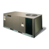
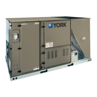
Do you have a question about the York ZE060 and is the answer not in the manual?
Alerts to potential injury, requires attention to signal words, and covers installation compliance, refrigerant handling, and fire/explosion hazards.
Includes CAUTIONs about code compliance and WARNINGs about improper installation and R-410A refrigerant.
Read instructions, ensure availability to consumer, and follow safety precautions and codes.
Emphasizes strict compliance with codes and potential hazards from improper installation or R-410A refrigerant.
Details wiring requirements, codes, grounding, and circuit protection for power and control connections.
Specifies the need for a disconnect, factory options, and cautions regarding mounting.
Covers power wiring sizing, transformer tap adjustments, and control wire sizing/length for thermostats.
Diagram illustrating typical field power wiring connections including contactors and disconnects.
Wiring diagram for Simplicity Lite controls, showing thermostat and UCB connections.
Wiring diagram for Smart Equipment control, detailing thermostat and UCB connections.
Guidelines for proper gas piping sizing based on flow rate, specific gravity, and length, referencing codes and tables.
Details gas piping recommendations, including drip legs, unions, pipe types, cleaning, and leak testing.
Emphasizes fire/explosion hazards, proper pipe dope for LP gas, and leak testing procedures.
Discusses conditional parameters, sensor presence, and function-specific menu items.
Outlines economizer drivers like minimum position, free cooling, loading, and outdoor air supply.
Procedure for measuring supply air CFM using static pressure readings and blower performance data.
Failure to properly adjust system airflow and static pressure can cause extensive system damage.
Describes what happens when the high-pressure limit switch opens and lockout conditions.
Details low-pressure limit switch monitoring and lockout conditions.
Explains freezestat operation and evaporator low limit sensor lockout conditions.
Lists safety controls monitored by the UCB for cooling, including pressure switches and freezestats.
Describes errors related to the electric heat temperature limit and its impact on blower operation.
Details the location and function of the temperature limit switch in the electric heat compartment.
Describes the step-by-step process for gas heating ignition, operation, and safety checks.
Details furnace shutdown conditions, auxiliary limits, and gas valve monitoring.
Explains the redundant gas valve operation and the function of the centrifugal switch.
Describes the roll-out switch function and pilot flame lockout conditions.
Pre-start checks for gas type, vent hoods, and pilot/main burner lighting.
Checks after heating operation begins, including gas leaks, manifold pressure, and supply gas pressure.
Instructions for adjusting manifold gas pressure using the regulator screws.
Procedure for checking natural gas input, measuring meter revolutions, and calculating consumption.
Troubleshooting steps if the compressor is not energizing but the blower is.
Troubleshooting steps if the blower motor is not energizing during a cooling call.
Explains compressor lockouts, ASCD, economizer wiring issues, and potential UCB faults.
Troubleshooting steps for the ignition control board, including LED indicators, voltage checks, and wiring verification.
Procedure for diagnosing and resolving issues with the centrifugal switch on the draft motor.
Troubleshooting steps for pilot flame issues, including flame sensor adjustment and burner assembly checks.
Troubleshooting steps for flame presence without a call for heat, involving gas valve and ICB checks.
Details the function of temperature limits and troubleshooting steps for limit trips and furnace shutdowns.
Troubleshooting for gas valve issues, including hard lockouts and power reset procedures.
Steps to take if the flame sense circuit fails, leading to a hard lockout.
Troubleshooting common heating issues like blower or draft motor not operating.
Explains Simplicity Lite flash codes for normal operation and errors, including LAST ERROR and TEST RESET functions.
Table listing Simplicity Lite UCB flash codes and their corresponding descriptions for troubleshooting.
Table listing Ignition Control Board flash codes and their descriptions for fault identification.
Continues UCB connections for refrigerant circuit safety switches, including overload relays.
Explains UCB connections for refrigerant circuit high and low-pressure switches for compressors.
Covers general start-up procedures, warranty statements, and equipment startup using LCD or MAP Gateway.
General safety warnings about lethal voltages and moving parts during startup checks.
Verifying proper operation of heating/cooling staging and variable frequency drive.
Final checks on control set points, options, panel security, and saving backup files.
| Cooling Capacity | 6.0 kW |
|---|---|
| Heating Capacity | 6.5 kW |
| Refrigerant | R410A |
| Outdoor Unit Weight | 42 kg |
| Power Supply | 220-240V, 50Hz |