EasyManua.ls Logo

York Sunline ZE Series User Manual

York Sunline ZE Series
77 pages
To Next Page IconTo Next Page
Page #1 background imageLoading...
Page #1 background image
R-410A
ZE SERIES
3 - 5 Ton
60 Hertz
5188235-YIM-E-0518
TABLE OF CONTENTS
General . . . . . . . . . . . . . . . . . . . . . . . . . . . . . . . . . . . . . . . . . . . . . 2
Installation . . . . . . . . . . . . . . . . . . . . . . . . . . . . . . . . . . . . . . . . . . . 5
Installation Safety Information . . . . . . . . . . . . . . . . . . . . . . . . . . 5
Limitations . . . . . . . . . . . . . . . . . . . . . . . . . . . . . . . . . . . . . . . . . 5
Location . . . . . . . . . . . . . . . . . . . . . . . . . . . . . . . . . . . . . . . . . . . 7
Rigging And Handling . . . . . . . . . . . . . . . . . . . . . . . . . . . . . . . . 7
Ductwork . . . . . . . . . . . . . . . . . . . . . . . . . . . . . . . . . . . . . . . . . 12
Condensate Drain . . . . . . . . . . . . . . . . . . . . . . . . . . . . . . . . . . 12
Compressors . . . . . . . . . . . . . . . . . . . . . . . . . . . . . . . . . . . . . . 12
Filters . . . . . . . . . . . . . . . . . . . . . . . . . . . . . . . . . . . . . . . . . . . . 13
Power And Control Wiring . . . . . . . . . . . . . . . . . . . . . . . . . . . . 13
Typical Field Power and Control Wiring . . . . . . . . . . . . . . . . . . . . 15
Typical Power Wiring . . . . . . . . . . . . . . . . . . . . . . . . . . . . . . . . 15
Typical Cool/Heat Control Wiring (Simplicity Lite ZE036-060). 15
Typical Cool/Heat Control Wiring (Smart Equipment™ ZE036-
060) . . . . . . . . . . . . . . . . . . . . . . . . . . . . . . . . . . . . . . . . . . . . . 16
Optional Electric Heat . . . . . . . . . . . . . . . . . . . . . . . . . . . . . . . 31
Options/Accessories . . . . . . . . . . . . . . . . . . . . . . . . . . . . . . . . 34
RRS Economizer Interface Overview . . . . . . . . . . . . . . . . . . . 34
Smart Equipment™ Economizer Sequences. . . . . . . . . . . . . . 35
Dry Bulb Changeover . . . . . . . . . . . . . . . . . . . . . . . . . . . . . . . 35
Single Enthalpy Changeover . . . . . . . . . . . . . . . . . . . . . . . . . . 35
Dual Enthalpy Changeover . . . . . . . . . . . . . . . . . . . . . . . . . . . 35
Auto . . . . . . . . . . . . . . . . . . . . . . . . . . . . . . . . . . . . . . . . . . . . . 35
Free Cooling Operation . . . . . . . . . . . . . . . . . . . . . . . . . . . . . . 35
Power Exhaust . . . . . . . . . . . . . . . . . . . . . . . . . . . . . . . . . . . . 36
Operation. . . . . . . . . . . . . . . . . . . . . . . . . . . . . . . . . . . . . . . . . 36
Checking Supply Air CFM . . . . . . . . . . . . . . . . . . . . . . . . . . . . 48
Operation . . . . . . . . . . . . . . . . . . . . . . . . . . . . . . . . . . . . . . . . . . . 49
Cooling Sequence Of Operation . . . . . . . . . . . . . . . . . . . . . . . 49
No Outdoor Air Options . . . . . . . . . . . . . . . . . . . . . . . . . . . . 49
Cooling Operation Errors . . . . . . . . . . . . . . . . . . . . . . . . . . . 49
Electric Heating Sequence Of Operations . . . . . . . . . . . . . . . . 51
Electric Heat Operation Errors . . . . . . . . . . . . . . . . . . . . . . . 51
Gas Heating Sequence Of Operations . . . . . . . . . . . . . . . . . . 52
Gas Heat Operation Errors . . . . . . . . . . . . . . . . . . . . . . . . . . . 52
Flash Codes or Error Messages . . . . . . . . . . . . . . . . . . . . . . . 53
Resets . . . . . . . . . . . . . . . . . . . . . . . . . . . . . . . . . . . . . . . . . . . 53
Heat Anticipator Setpoints . . . . . . . . . . . . . . . . . . . . . . . . . . . . 53
Start-up (Cooling) . . . . . . . . . . . . . . . . . . . . . . . . . . . . . . . . . . . . 54
Start-up (Gas Heat) . . . . . . . . . . . . . . . . . . . . . . . . . . . . . . . . . . . 54
Checking Gas Input . . . . . . . . . . . . . . . . . . . . . . . . . . . . . . . . . . . 56
Troubleshooting (Simplicity Lite Only) . . . . . . . . . . . . . . . . . . . . . 56
Smart Equipment™ Control Board Navigation Components . . . . 65
Start-Up Sheet . . . . . . . . . . . . . . . . . . . . . . . . . . . . . . . . . . . . . 72
LIST OF TABLES
1 ZE036-060 Unit Limitations . . . . . . . . . . . . . . . . . . . . . . . . . . . 6
2 ZE036-060 . . . . . . . . . . . . . . . . . . . . . . . . . . . . . . . . . . . . . . . . 8
3 ZE036-060 Unit Accessory Weights . . . . . . . . . . . . . . . . . . . . 8
4 ZE036-060 Unit Clearances . . . . . . . . . . . . . . . . . . . . . . . . . 10
5 ZE036-060 Utilities Entry . . . . . . . . . . . . . . . . . . . . . . . . . . . . 11
6 Control Wire Sizes . . . . . . . . . . . . . . . . . . . . . . . . . . . . . . . . . 14
7 Electrical Data . . . . . . . . . . . . . . . . . . . . . . . . . . . . . . . . . . . . 17
8 ZE036-060 Physical Data . . . . . . . . . . . . . . . . . . . . . . . . . . . 29
9 Electric Heat Minimum Supply Air . . . . . . . . . . . . . . . . . . . . . 31
10 Gas Heat Application Data . . . . . . . . . . . . . . . . . . . . . . . . . . 31
11 Gas Pipe Sizing - Capacity of Pipe . . . . . . . . . . . . . . . . . . . . 32
12 Smart Equipment™ Economizer Board Details . . . . . . . . . . 3 7
13 Altitude/Temperature Correction Factors . . . . . . . . . . . . . . . 41
14 ZE Blower Performance Side Duct . . . . . . . . . . . . . . . . . . . . 44
15 ZE Blower Performance Bottom Duct . . . . . . . . . . . . . . . . . . 46
16 Belt Drive RPM Selection . . . . . . . . . . . . . . . . . . . . . . . . . . . 47
17 Indoor Blower Specifications (Belt Drive) . . . . . . . . . . . . . . . 47
18 Power Exhaust Specifications . . . . . . . . . . . . . . . . . . . . . . . . 47
19 Additional Static Resistance . . . . . . . . . . . . . . . . . . . . . . . . . 48
20 Electric Heat Limit Setting . . . . . . . . . . . . . . . . . . . . . . . . . . . 51
21 Electric Heat Anticipator Setpoints . . . . . . . . . . . . . . . . . . . . 52
22 Single Stage Gas Heat Limit Control Setting . . . . . . . . . . . . 53
23 2 Stage Gas Heat Limit Control Setting . . . . . . . . . . . . . . . . 53
24 Gas Heat Anticipator Setpoints . . . . . . . . . . . . . . . . . . . . . . . 54
25 Gas Rate-Cubit Feet per Hour . . . . . . . . . . . . . . . . . . . . . . . 56
26 ZE036 (3.0 Ton) Operating Pressures . . . . . . . . . . . . . . . . . 59
27 ZE048 (4.0 Ton) Operating Pressures . . . . . . . . . . . . . . . . . 59
28 ZE060 (5.0 Ton) Operating Pressures . . . . . . . . . . . . . . . . . 60
29 Simplicity Lite Unit Control Board Flash Codes . . . . . . . . . . 64
30 Ignition Control Board Flash Codes . . . . . . . . . . . . . . . . . . . 64
31 Smart Equipment™ UCB Details . . . . . . . . . . . . . . . . . . . . . 65
32 Cable for FC Buses and SA Buses in Order of Preference . 71
LIST OF FIGURES
1 ZE036-060 Component Location . . . . . . . . . . . . . . . . . . . . . . 6
2 Unit 4 Point Load Weight . . . . . . . . . . . . . . . . . . . . . . . . . . . . 8
3 Unit 6 Point Load Weight . . . . . . . . . . . . . . . . . . . . . . . . . . . . 8
4 Center of Gravity . . . . . . . . . . . . . . . . . . . . . . . . . . . . . . . . . . 8
5 ZE036-060 Cooling Only/Electric Heat Front View Physical
Dimensions . . . . . . . . . . . . . . . . . . . . . . . . . . . . . . . . . . . . . . . 9
6 ZE036-060 Cooling Only/Gas Heat Front View Physical
Dimensions . . . . . . . . . . . . . . . . . . . . . . . . . . . . . . . . . . . . . . . 9
7 ZE036-060 Fixed Outdoor Air Motorized Damper Rain Hood
Physical Dimensions . . . . . . . . . . . . . . . . . . . . . . . . . . . . . . 10
8 ZE036-060 Disconnect Location . . . . . . . . . . . . . . . . . . . . . 10
9 ZE036-060 Unit Side Duct Openings . . . . . . . . . . . . . . . . . . 11
10 ZE036-060 Roof Curb . . . . . . . . . . . . . . . . . . . . . . . . . . . . . 11
11 Condensate Drain . . . . . . . . . . . . . . . . . . . . . . . . . . . . . . . . . 12
12 Compressor Restraining Bracket . . . . . . . . . . . . . . . . . . . . . 13
13 Typical Field Power and Simplicity Lite Control Wiring . . . . 15
14 Typical Smart Equipment™ Control Wiring . . . . . . . . . . . . . 16
15 Side Entry Gas Piping . . . . . . . . . . . . . . . . . . . . . . . . . . . . . 32
16 Bottom Entry Gas Piping . . . . . . . . . . . . . . . . . . . . . . . . . . . 32
17 Vent And Combustion Air Hood . . . . . . . . . . . . . . . . . . . . . . 34
18 RRS Economizer LCD and Keypad Layout. . . . . . . . . . . . . 3 4
19 SE-ECO1001-0 Economizer Controller . . . . . . . . . . . . . . . . 37
20 Belt Adjustment . . . . . . . . . . . . . . . . . . . . . . . . . . . . . . . . . . 41
21 Altitude/Temperature Correction Factors . . . . . . . . . . . . . . . 42
22 Pressure Drop Across Coil . . . . . . . . . . . . . . . . . . . . . . . . . . 48
23 Gas Valve Piping . . . . . . . . . . . . . . . . . . . . . . . . . . . . . . . . . 52
24 Typical Single Stage Gas Valves . . . . . . . . . . . . . . . . . . . . . 55
25 Typical 2 Stage Gas Valves . . . . . . . . . . . . . . . . . . . . . . . . . 55
26 Proper Flame Adjustment . . . . . . . . . . . . . . . . . . . . . . . . . . 55
27 Typical Flame Appearance . . . . . . . . . . . . . . . . . . . . . . . . . 55
28 Simplicity Lite Control Board . . . . . . . . . . . . . . . . . . . . . . . . 64
29 Smart Equipment™ Unit Control Board . . . . . . . . . . . . . . . . 65

Table of Contents

Question and Answer IconNeed help?

Do you have a question about the York Sunline ZE Series and is the answer not in the manual?

York Sunline ZE Series Specifications

General IconGeneral
BrandYork
ModelSunline ZE Series
CategoryAir Conditioner
LanguageEnglish

Summary

General Unit Information and Safety

Safety Considerations and Signal Words

Highlights signal words (DANGER, WARNING, CAUTION) and the safety alert symbol for potential injury.

Installation Safety Warnings

General warnings about installation compliance, hazards, and proper operation.

R-410A Refrigerant Safety

System uses R-410A refrigerant; use compatible servicing equipment.

Installation Requirements and Cautions

Unit Inspection for Transit Damage

Inspect unit for transit damage; note any damage on carrier's freight bill.

Installation Compliance Warnings

Strict compliance with installation instructions and codes is mandatory for product installation.

Installation Hazard Warning

Improper installation may create conditions causing personal injury or property damage.

Product Nomenclature and Identification

Product Category and Identification

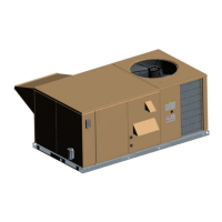
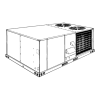
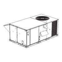
Identifies the unit as a single package, R-410A unit, and explains model number components.

Cooling and Heat Type Specifications

Specifies cooling capacity, heat type (electric/gas), and heat capacity in MBH or kW.

Blower, Voltage, and Sensor Options

Details blower type, voltage, sensor options, service options, and outdoor air options.

Installation Guidelines and Safety

Installation Safety Information

Read instructions, ensure availability to consumer, and follow all safety warnings.

Installation Limitations and Codes

Lists codes and standards that must be followed for installation in the US and Canada.

Low Temperature Operation Caution

Control boards operate down to 0°F for people cooling; consult for process cooling below 30°F.

ZE036-060 Component Location

ZE036-060 Unit Limitations

Installation Location and Handling

Condenser Airflow Obstruction Warning

Do not obstruct condenser air discharge, combustion air inlet, or vent outlets with structures or shrubs.

Rigging and Handling Procedures

Instructions for safely moving and rigging the unit using lifting holes and spreader bars.

Required Installation Clearances

Specifies required clearances for proper operation and service according to codes.

Unit Weight and Load Distribution

Accessory Weight Specifications

Lists shipping and operating weights for common accessories.

ZE036-060 Front View Physical Dimensions

ZE036-060 Damper Rain Hood Dimensions

ZE036-060 Unit Clearances

ZE036-060 Disconnect Location

ZE036-060 Unit Side Duct Openings

ZE036-060 Utilities Entry

ZE036-060 Roof Curb

Ductwork Installation and Component Care

Ductwork Fastening Caution

Do not insert screws through casing when fastening ductwork; insulate outdoor ductwork.

Condensate Drain Plumbing

Instructions for plumbing the condensate drain line, including trapping.

Compressor Handling and Safety

Information on scroll compressors, R-410A refrigerant, and POE oil handling.

Unit Protection, Filters, and Wiring

Panel Latch Airtight Seal Caution

Ensure panel latches are properly positioned for an airtight seal.

Power and Control Wiring Requirements

Requirements for field wiring, fuses, disconnects, grounding, and wire sizing.

Electrical Connection Safety Cautions

Cautions regarding high-leg delta supply and water-proof connectors.

Optional Features and Wiring

Transformer Tap Adjustment Caution

Transformer tap adjustment for different voltages for convenience outlet.

Thermostat Wiring Guidelines

Guidelines for thermostat location, wire count, and maximum length.

Typical Field Wiring Diagrams

Typical Power Wiring Diagram

Wiring diagram for single and three-phase power supply connections.

Simplicity Lite Control Wiring Diagram

Detailed wiring diagram for Simplicity Lite control system.

Smart Equipment™™ Control Wiring Diagram

Electrical Data Specifications

Electrical Data Table Continuation

Electrical Data: Belt Drive High Static

Electrical Data: Belt Drive High Static Continued

Electrical Data: Direct Drive

Electrical Data: Direct Drive Continued

Electrical Data: With Convenience Outlet (Belt Drive)

Electrical Data: With Convenience Outlet (Belt Drive) Continued

Electrical Data: With Convenience Outlet (Belt Drive High Static)

Electrical Data: With Convenience Outlet (Belt Drive High Static) Continued

Electrical Data: With Convenience Outlet (Direct Drive)

Electrical Data: With Convenience Outlet (Direct Drive) Continued

ZE036-060 Physical Data

ZE036-060 Physical Data Continued

Optional Heating Features

Minimum Supply Air for Electric Heat

Specifies minimum supply air CFM required for various electric heat kW options.

Gas Heat Application Data

Provides gas heat capacity, input/output, rate, and temperature rise data.

Gas Piping Installation and Safety

Gas Piping Safety Warnings

Warnings about propane solvent properties and leak testing without flame.

Gas Connection Procedures

Details gas supply line routing, typical arrangements, and piping recommendations.

Gas Piping Safety and Vent Hoods

LP Gas Equipment Requirements

Requirements for LP gas equipment, pressure, and piping.

Unit Options and Accessories

Electric Heat Installation

Information on electric heater installation and power requirements.

Economizer/Damper Installation

Details on optional economizer, damper, and rain hood installation.

RRS Economizer Interface Overview

Guide to using the RRS Economizer controller's interface.

Economizer Control Sequences

Economizer Minimum Position Setting

Setting the economizer minimum position for occupied mode.

Free Cooling Operation Types

Describes four types of free cooling: dry bulb, enthalpy, dual enthalpy, and auto.

Unit Operation Sequences

Cooling Sequence of Operation Details

Detailed sequence for cooling, including economizer and compressor staging.

Cooling Operation Errors and Safety Limits

Groups errors, limit switches, and low ambient cooling.

Power Exhaust Operation

Economizer operation combined with power exhaust.

Economizer Operation Modes

Discusses single/dual enthalpy, power exhaust, and damper controls.

Smart Equipment™™ Economizer Board Details

Economizer Board Terminal Descriptions

Details the economizer board terminals and their functions.

Economizer Board Status LEDs

Explains the status indicated by the LEDs on the economizer board.

Smart Equipment™™ Economizer Board Details Continued

Smart Equipment™™ Economizer Board Details Continued

Smart Equipment™™ Economizer Board Details Continued

Indoor Air Quality Sensor Function

How the IAQ sensor affects economizer operation and ventilation.

Motor Phasing and Rotation Checks

Correct phasing for motors and compressors; how to correct misphased connections.

Blower and Drive System Checks

Altitude and Temperature Corrections

How to correct blower performance data for altitude and temperature.

Altitude Correction Examples

Drive Selection Process

Blower Performance Selection Example

Walkthrough of the drive selection process using performance tables.

ZE Blower Performance Side Duct

ZE Direct Drive Side Duct Blower Performance

Belt Drive RPM Selection

Table for selecting belt drive RPM based on unit size and motor/sheave settings.

Power Exhaust Specifications

Specifications for power exhaust motors, including voltage, HP, and electrical data.

ZE Blower Performance Bottom Duct

ZE Direct Drive Bottom Duct Blower Performance

Checking Supply Air CFM

Airflow Measurement Warning

Improper air quantity/static pressure adjustment can cause extensive system damage.

Static Resistance and Pressure Drop Data

Combines additional static resistance values and pressure drop graph.

Unit Operation Sequences

Cooling Sequence of Operation Details

Detailed sequence for cooling, including economizer and compressor staging.

Cooling Operation Errors Overview

Groups errors, limit switches, and low ambient cooling.

Economizer Operation Modes

Discusses single/dual enthalpy, power exhaust, and damper controls.

Cooling Operation Safety and Control Limits

Low Ambient Cooling Procedures

Specific modes for low ambient cooling operation.

Monitored Safety Control Inputs

Lists safety controls monitored by the unit control board.

Compressor Protection and Electric Heat Operation

Electric Heat Limit Setting Data

Specifies temperature limit settings for various electric heat configurations.

Gas Heating Operation and Controls

Temperature Limit Functions

Function of primary and auxiliary temperature limits in the furnace.

Gas Heating Troubleshooting and Safety Devices

Gas Heat Limit Control Settings

Limit control settings for single-stage and two-stage gas heat.

Gas Heat Start-up Procedures

Cooling Start-up Checklist and Operations

Essential checks and operations before starting the unit for cooling.

Gas Heat Start-up Checklist and Operations

Essential checks and operations before starting the unit for gas heating.

Gas Valve and Burner Adjustment Procedures

Typical Gas Valve Diagrams

Diagrams of typical single-stage and two-stage gas valves.

Proper Flame Adjustment Guide

Visual guide and instructions for proper pilot and burner flame adjustment.

Burner Assembly Service

Instructions for checking or changing burners, pilot, or orifices.

Gas Input Check and Temperature Rise

Troubleshooting Simplicity Lite Controls

Troubleshooting specific issues for Simplicity Lite control systems, including warnings.

Simplicity Lite Troubleshooting Steps

Compressor Not Energizing Troubleshooting

Troubleshooting compressor not operating when M1 contactor is engaged.

Simplicity Lite Troubleshooting Continued

ZE Operating Pressures Data

Gas Heat Troubleshooting and Control Codes

Gas Heat Troubleshooting Safety Warnings

Groups warnings and cautions related to gas heat troubleshooting.

Flash Code Troubleshooting Procedures

How to interpret and troubleshoot flash codes from the control boards.

Ignition Control Board and Centrifugal Switch Troubleshooting

Pilot Flame Lockout Troubleshooting

How pilot flame lockouts are handled and troubleshooting steps.

Gas Heating Safety Switch Troubleshooting

Symptomatic Troubleshooting Guide

Step-by-step troubleshooting for common operational issues.

Symptomatic Troubleshooting Steps

Simplicity Lite Unit Flash Codes

Simplicity Lite Control Board Flash Codes

Table detailing Simplicity Lite flash codes and error descriptions.

Ignition Control Board Flash Codes

Table detailing Ignition Control Board flash codes and error descriptions.

Smart Equipment™™ Control Board Navigation

Smart Equipment™™ UCB Terminal Details

Details the Smart Equipment™™ Unit Control Board terminals and their functions.

Smart Equipment™™ UCB Terminal Details Continued

Smart Equipment™™ UCB Terminal Details Continued

Smart Equipment™™ UCB Terminal Details Continued

Smart Equipment™™ UCB Terminal Details Continued

Smart Equipment™™ UCB Terminal Details Continued

Cable Specifications for Buses

Start-Up Sheet Procedures

Start-Up Checklist and Operations

Checklist for verifying installation and startup procedures.

Warranty Statement Information

Information regarding the warranty policy for the equipment.

Safety Warnings and Application Information

Design Application Data Fields

Fields to be filled by the specifying engineer for proper application.

Inspection and Reference Checklists

General Inspection Checklist Items

Checklist for general inspection points before operation.

Air Moving Component Inspection

Checklist for inspecting blower and drive components.

Economizer System Inspection

Checklist for verifying economizer settings and operation.

Operating Measurements - Air Flow

Electrical Data Recording

Table for recording electrical data during operation measurements.

Operating Measurements - Cooling

Refrigerant Safety Checks

Specific safety checks for the refrigerant system.

Operating Measurements - Gas Heating

Operational Measurements - Staging Controls

Verify Staging Control Operation

Verifying correct energization of heating/cooling stages based on demand.

Verify Variable Frequency Drive Operation

Checking VFD modulation with duct pressure changes.

Final Inspection and Product Concerns

Combines final inspection and recording product deficiencies.

Related product manuals